For 1990-2009 cars only
Caution: Refer to Brake Fluid Irritant Caution in the Preface section.
Notice: Refer to Brake Fluid Effects on Paint and Electrical Components Notice in the Preface section.
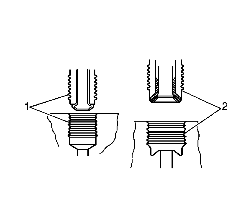
Notice: There is a first design and second design of brake pipe flare for the hydraulic
brake pipes and system components used on this vehicle. Do NOT mis-match flare types.
If the flare types are mis-matched, damage to the pipes and/or components, and/or
a brake fluid leak may occur.
• First design, ISO flare (1) • Second design, double inverted flare (2)
Removal Procedure
- Disconnect the negative battery cable. Refer to Battery Negative Cable Disconnection and Connection in Engine Electrical.
- Remove the cover from the underhood electrical center.
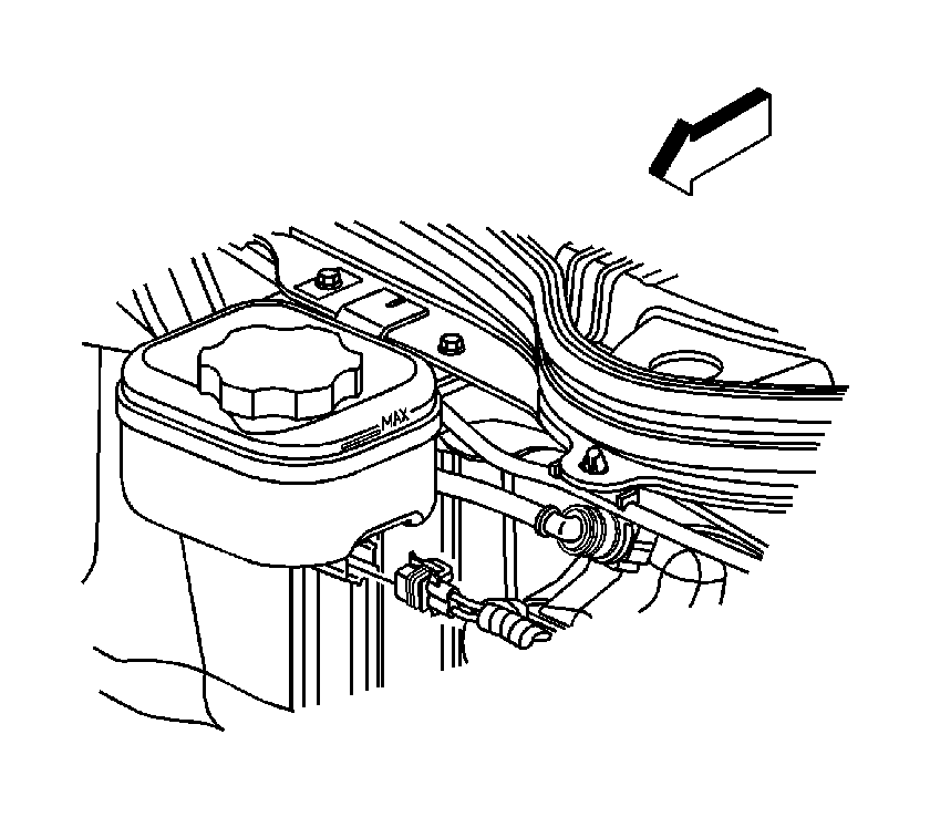
- Pull back on the connector position assurance (CPA) tab of the electrical connector, then disconnect the connector from the brake fluid level sensor.
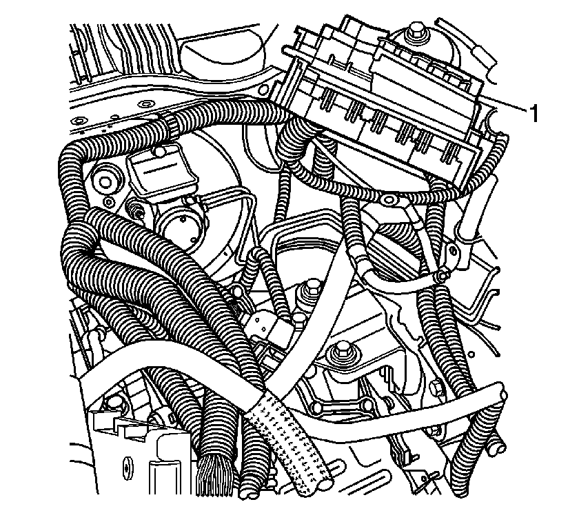
- Remove the underhood electrical center bracket from the vehicle and reposition the electrical center (1) to access the brake master cylinder. Refer to Underhood Electrical Center or Junction Block Bracket Replacement in Wiring Systems.
- Remove the brake master cylinder auxiliary reservoir. Refer to Brake Master Cylinder Auxiliary Reservoir Replacement .
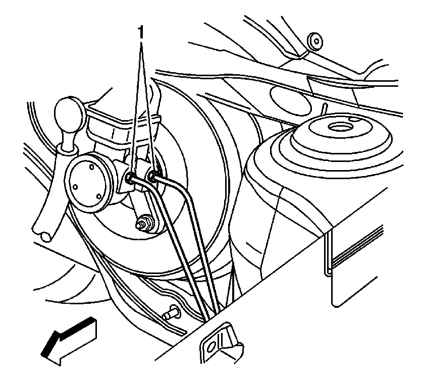
- Disconnect the brake pipes (1) from the master cylinder.
- Cap the open brake pipe fitting ends to prevent brake fluid loss and contamination.
- Remove the master cylinder mounting nuts.
- Remove the master cylinder from the vacuum brake booster.
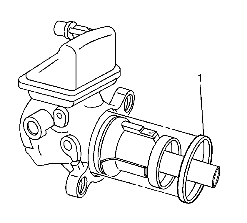
- If the master cylinder is to be reused, inspect the master cylinder-to-vacuum brake booster seal (1) for damage. Replace the seal (1) if necessary.

Installation Procedure
- Bench bleed the master cylinder. Refer to Master Cylinder Bench Bleeding .
- Check to ensure that the master cylinder-to-vacuum brake booster seal (1) is properly seated into the recessed groove on the master cylinder.
- Install the master cylinder to the vacuum brake booster.
- Install the brake master cylinder mounting nuts.
- Remove the caps from the brake pipe ends.
- Connect the brake pipe fittings (1) at the master cylinder.
- Install the brake master cylinder auxiliary reservoir. Refer to Brake Master Cylinder Auxiliary Reservoir Replacement .
- Install the underhood electrical center bracket to the vehicle and install the electrical center (1) into position on the bracket. Refer to Underhood Electrical Center or Junction Block Bracket Replacement in Wiring Systems.
- Connect the electrical connector to the brake fluid level sensor, then press forward on the CPA tab of the connector to secure.
- Install the cover to the underhood electrical center.
- Connect the negative battery cable. Refer to Battery Negative Cable Disconnection and Connection in Engine Electrical.
- Bleed the hydraulic brake system. Refer to Hydraulic Brake System Bleeding .


Notice: Refer to Fastener Notice in the Preface section.
Tighten
Tighten the nuts to 20 N·m (15 lb ft).

Tighten
| • | Tighten the fittings, first design, ISO flare to 19 N·m (14 lb ft). |
| • | Tighten the fittings, second design, double inverted flare to 18 N·m (13 lb ft). |


