Caution: Refer to Brake Fluid Irritant Caution in the Preface section.
Notice: Refer to Brake Fluid Effects on Paint and Electrical Components Notice in the Preface section.
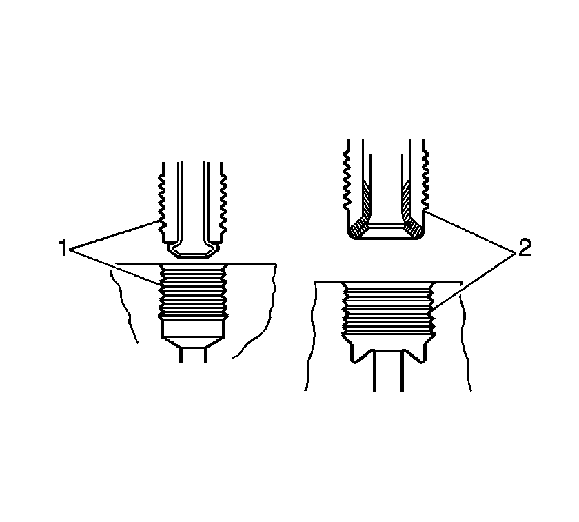
Notice: There is a first design and second design of brake pipe flare for the hydraulic
brake pipes and system components used on this vehicle. Do NOT mis-match flare types.
If the flare types are mis-matched, damage to the pipes and/or components, and/or
a brake fluid leak may occur.
• First design, ISO flare (1) • Second design, double inverted flare (2)
Removal Procedure
- Place a shop towel under the proportioning valve assembly to catch any brake fluid loss.
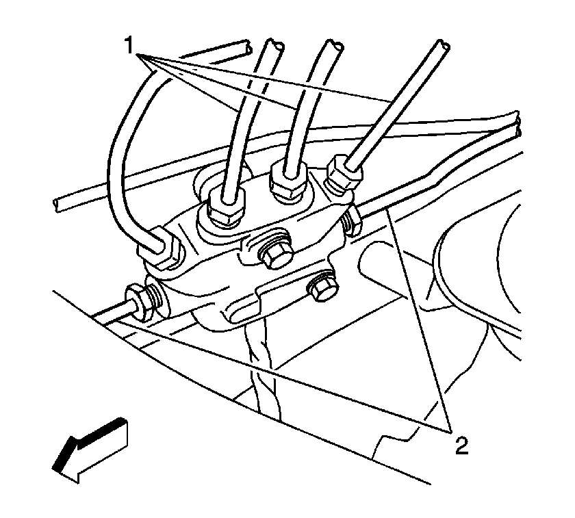
- Disconnect the caliper and wheel cylinder brake pipes (1) from the proportioning valve assembly.
- Cap or plug the brake pipe ends to prevent brake fluid loss and contamination.
- Disconnect the master cylinder brake pipes (2) from the proportioning valve assembly.
- Cap or plug the brake pipe ends to prevent brake fluid loss and contamination.
- If the proportioning valve is to be reused, plug the ports to prevent brake fluid loss and contamination.
- Release the forward lamp wiring harness from the proportioning valve assembly bracket.
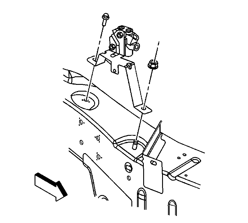
- Remove the proportioning valve assembly bracket mounting nut and mounting bolt.
- Remove the proportioning valve assembly from the vehicle.

Important: Prior to disconnecting the brake pipes from the proportioning valve assembly, note the locations of the brake pipes to the valve assembly, to aid during installation.

Installation Procedure
- Install the proportioning valve assembly to the vehicle.
- Install the proportioning valve assembly bracket mounting nut and mounting bolt.
- Secure the forward lamp wiring harness to the proportioning valve assembly bracket.
- Remove the plugs from the proportioning valve assembly ports.
- Remove the caps or plugs from the master cylinder brake pipe ends.
- Connect the master cylinder brake pipes (2) to the proportioning valve assembly.
- Tighten the brake pipe fittings at the proportioning valve assembly.
- Remove the caps or plugs from the caliper and wheel cylinder brake pipe ends.
- Connect the caliper and wheel cylinder brake pipes (1) to the proportioning valve assembly.
- Tighten the brake pipe fittings at the proportioning valve assembly.
- Bleed the hydraulic brake system. Refer to Hydraulic Brake System Bleeding .
- Remove the shop towel and discard into an approved container.

Notice: Refer to Fastener Notice in the Preface section.
Tighten
| • | Tighten the nut to 25 N·m (18 lb ft). |
| • | Tighten the bolt to 25 N·m (18 lb ft). |

Tighten
| • | Tighten the fittings, first design, ISO flare to 19 N·m (14 lb ft). |
| • | Tighten the fittings, second design, double inverted flare to 18 N·m (13 lb ft). |
Tighten
| • | Tighten the fittings, first design, ISO flare to 19 N·m (14 lb ft). |
| • | Tighten the fittings, second design, double inverted flare to 18 N·m (13 lb ft). |
