Tools Required
J 38400 Brake Shoe Spanner and Spring Remover
Caution: Refer to Brake Dust Caution in the Preface section.
Caution: Refer to Brake Fluid Irritant Caution in the Preface section.
Notice: Refer to Brake Fluid Effects on Paint and Electrical Components Notice in the Preface section.

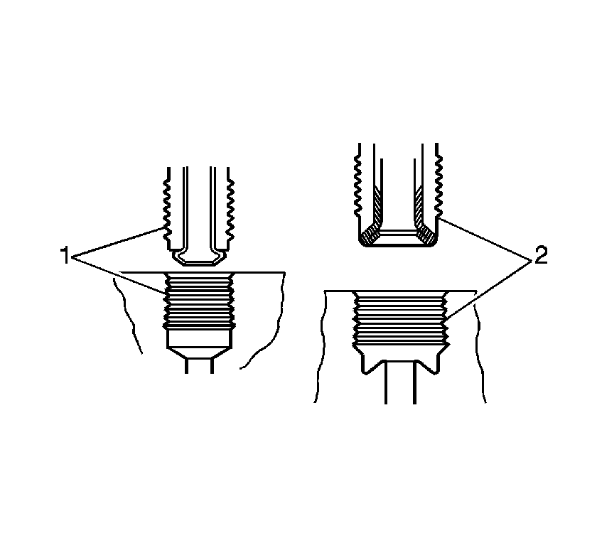
Notice: There is a first design and second design of brake pipe flare for the hydraulic
brake pipes and system components used on this vehicle. Do NOT mis-match flare types.
If the flare types are mis-matched, damage to the pipes and/or components, and/or
a brake fluid leak may occur.
• First design, ISO flare (1) • Second design, double inverted flare (2)
Removal Procedure
- Raise and support the vehicle. Refer to Lifting and Jacking the Vehicle in General Information.
- Remove the tire and wheel assembly. Refer to Tire and Wheel Removal and Installation in Tires and Wheels.
- Remove the brake drum. Refer to Brake Drum Replacement .
- Clean any debris and contaminants from around the wheel cylinder.
- Remove the wheel cylinder bleeder cap and valve (2).
- Disconnect the brake pipe fitting (1) from the wheel cylinder. Cap the exposed brake pipe end to prevent fluid loss and contamination.
- Remove the wheel cylinder mounting bolts (3).
- Using the J 38400 , spread the top of the brakes shoes apart, then remove the wheel cylinder from the brake backing plate.


Installation Procedure
- Using the J 38400 , spread the top of the brakes shoes apart, then install the wheel cylinder to the brake backing plate.
- Install the wheel cylinder mounting bolts (3).
- Remove the cap from the brake pipe end.
- Connect the brake pipe fitting (1) at the wheel cylinder.
- Install the wheel cylinder bleeder valve.
- Install the brake drum. Refer to Brake Drum Replacement .
- Bleed the hydraulic brake system. Refer to Hydraulic Brake System Bleeding in Hydraulic Brakes.
- Install the bleeder valve cap.
- Adjust the drum brakes. Refer to Drum Brake Adjustment .
- Install the tire and wheel assembly. Refer to Tire and Wheel Removal and Installation in Tires and Wheels.
- Lower the vehicle.

Notice: Refer to Fastener Notice in the Preface section.

Tighten
Tighten the bolts to 16 N·m (12 lb ft).
Tighten
Tighten the fitting, first or second design to 19 N·m
(14 lb ft).
Tighten
Tighten the valve to 8 N·m (71 lb in).
