GM Service Manual Online
For 1990-2009 cars only
Figure 1:

Module Power, Ground, Serial Data and MIL
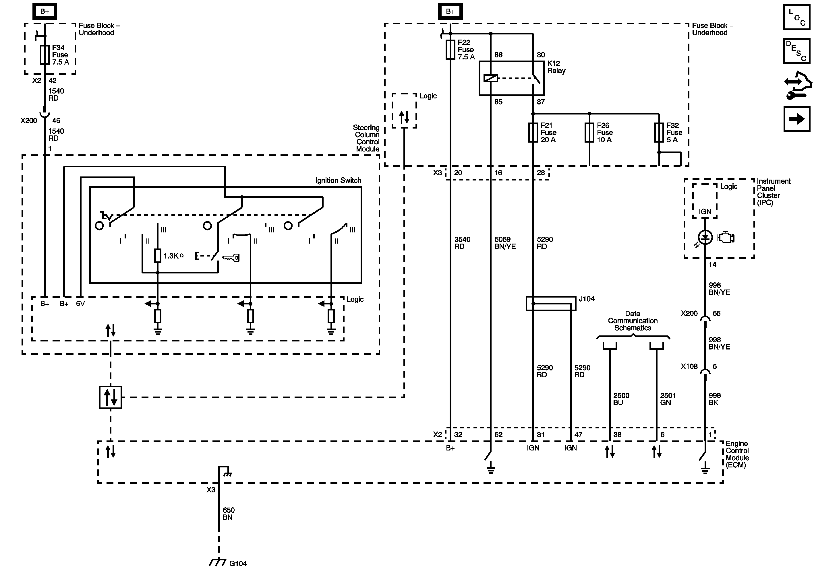

Object Number: 2030180  Size: FS
Master Electrical Component List
Engine Control Module Description
Control Module References
5-Volt and Low References
B+ Bus 2 of 2
Fuse Block - Underhood F34 Fuse and Ignition Switch
B+ Bus 2 of 2
Fuse Block - Underhood F28, F10, F22, F2, F1, and F36 Fuses
GM High Speed Serial Data (CAN C)
G100, G103, G104, G105 and G106
Figure 2:

5-Volt and Low References


Object Number: 2030183  Size: FS
Master Electrical Component List
Engine Control Module Description
Control Module References
Engine Data Sensors - Pressure, Temperature, and Throttle Controls
Module Power, Ground, Serial Data and MIL
Figure 3:

Engine Data Sensors - Pressure, Temperature, and Throttle Controls


Object Number: 2030186  Size: FS
Master Electrical Component List
Throttle Actuator Control (TAC) System Description
Control Module References
Engine Data Sensors - HO2s
5-Volt and Low References
Module Power, Ground, Serial Data and MIL
Fuse Block - Underhood F5, F21, F26, and F32 Fuses
Figure 4:

Engine Data Sensors - HO2S


Object Number: 2030188  Size: FS
Master Electrical Component List
Fuel System Description
Control Module References
Ignition Controls - Ignition Control Module (ICM)
Engine Data Sensors - Pressure, Temperature, and Throttle Controls
Module Power, Ground, Serial Data and MIL
Fuse Block - Underhood F5, F21, F26, and F32 Fuses
Figure 5:

Ignition Controls - Ignition Control Module (ICM)


Object Number: 2030191  Size: FS
Master Electrical Component List
Electronic Ignition (EI) System Description
Control Module References
Ignition Controls - Camshaft Sensors/Actuators, Knock Sensor
Engine Data Sensors - HO2s
B+ Bus 2 of 2
G100, G103, G104, G105 and G106
Figure 6:

Ignition Controls - Camshaft Sensors/Actuators, Knock Sensor


Object Number: 2030193  Size: FS
Master Electrical Component List
Electronic Ignition (EI) System Description
Control Module References
Engine Data Sensors - Intake Manifold Tuning (IMT) Solenoid Valve, Intake Manifold Tuning Valve (IMTV) Sensor, and Barometric Pressure (BARO) Sensor
Ignition Controls - Ignition Control Module (ICM)
Module Power, Ground, Serial Data and MIL
Fuse Block - Underhood F5, F21, F26, and F32 Fuses
Engine Data Sensors - Intake Manifold Tuning (IMT) Solenoid Valve, Intake Manifold Tuning Valve (IMTV) Sensor, and Barometric Pressure (BARO) Sensor
Figure 7:

Engine Data Sensors - Intake Manifold Tuning (IMT) Solenoid Valve, Intake Manifold Tuning Valve (IMTV) Sensor, and Barometric Pressure (BARO) Sensor


Object Number: 2030194  Size: FS
Master Electrical Component List
Engine Control Module Description
Control Module References
Fuel Controls - Fuel Injectors and Fuel Pump
Ignition Controls - Camshaft Sensors/Actuators, Knock Sensor
Module Power, Ground, Serial Data and MIL
Fuse Block - Underhood F5, F21, F26, and F32 Fuses
5-Volt and Low References
Figure 8:

Fuel Controls - Fuel Injectors and Fuel Pump


Object Number: 2030197  Size: FS
Master Electrical Component List
Fuel System Description
Control Module References
Fuel Controls - EVAP Controls and Fuel Tank Pressure Sensor
Engine Data Sensors - Intake Manifold Tuning (IMT) Solenoid Valve, Intake Manifold Tuning Valve (IMTV) Sensor, and Barometric Pressure (BARO) Sensor
B+ Bus 2 of 2
Gauges and Indicators
G401
Figure 9:

Fuel Controls - EVAP Controls and Fuel Tank Pressure Sensor


Object Number: 2030199  Size: FS
Master Electrical Component List
Evaporative Emission Control System Description
Control Module References
Monitored/Controlled Subsystem References
Fuel Controls - Fuel Injectors and Fuel Pump
Module Power, Ground, Serial Data and MIL
Fuse Block - Underhood F5, F21, F26, and F32 Fuses
5-Volt and Low References
Figure 10:

Monitored/Controlled Subsystem References


Object Number: 2030201  Size: FS
Master Electrical Component List
Engine Control Module Description
Control Module References
Fuel Controls - EVAP Controls and Fuel Tank Pressure Sensor
Compressor Controls
Gauges and Indicators
Hydraulic Brake Schematics
Brake, Hazard, and Turn Signal Switching
Driver Information Center (DIC)
Cruise Control
Starting System
MNF with C41 or M25
Engine Mechanical