For 1990-2009 cars only
Special Tools
| • | J 23327 Clutch Spring Compressor |
| • | J 45124 Removal Bridge |
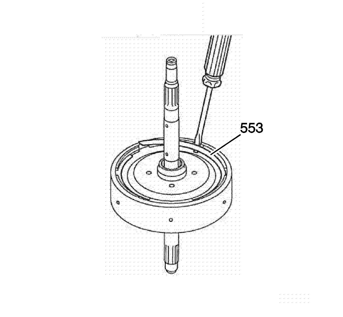
- Remove the sun gear input flange retaining ring (553) with a screwdriver.
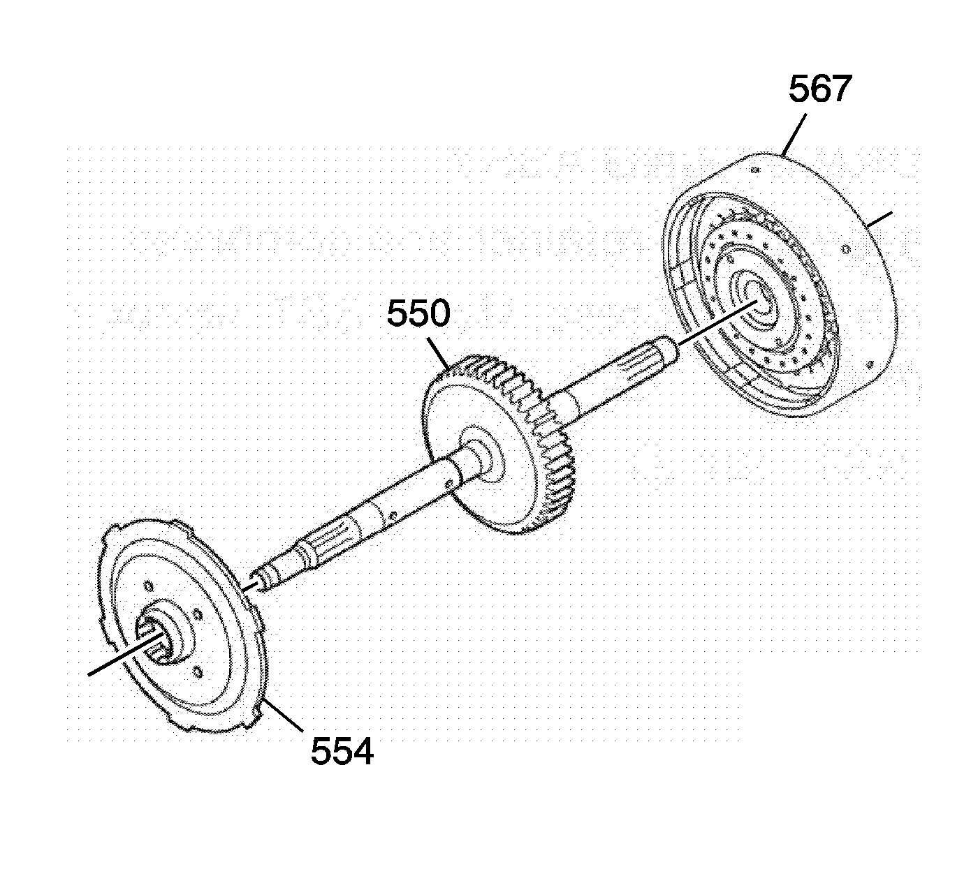
- Remove the sun gear input flange (554).
- Separate the reverse gear clutch drum (567) and the input shaft (550).
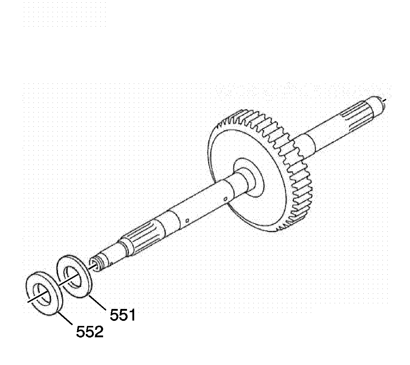
- Remove the input shaft thrust bearing (551) and the input shaft thrust bearing race (552).
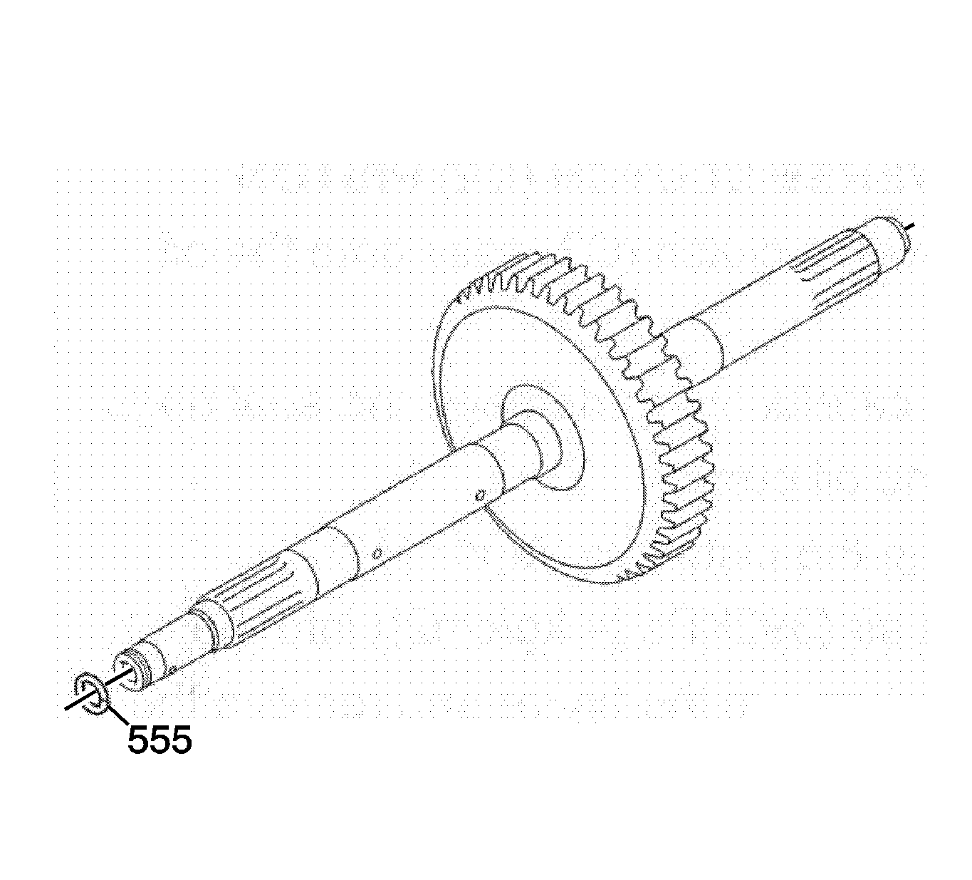
- Remove the input shaft seal ring-slotted (555).
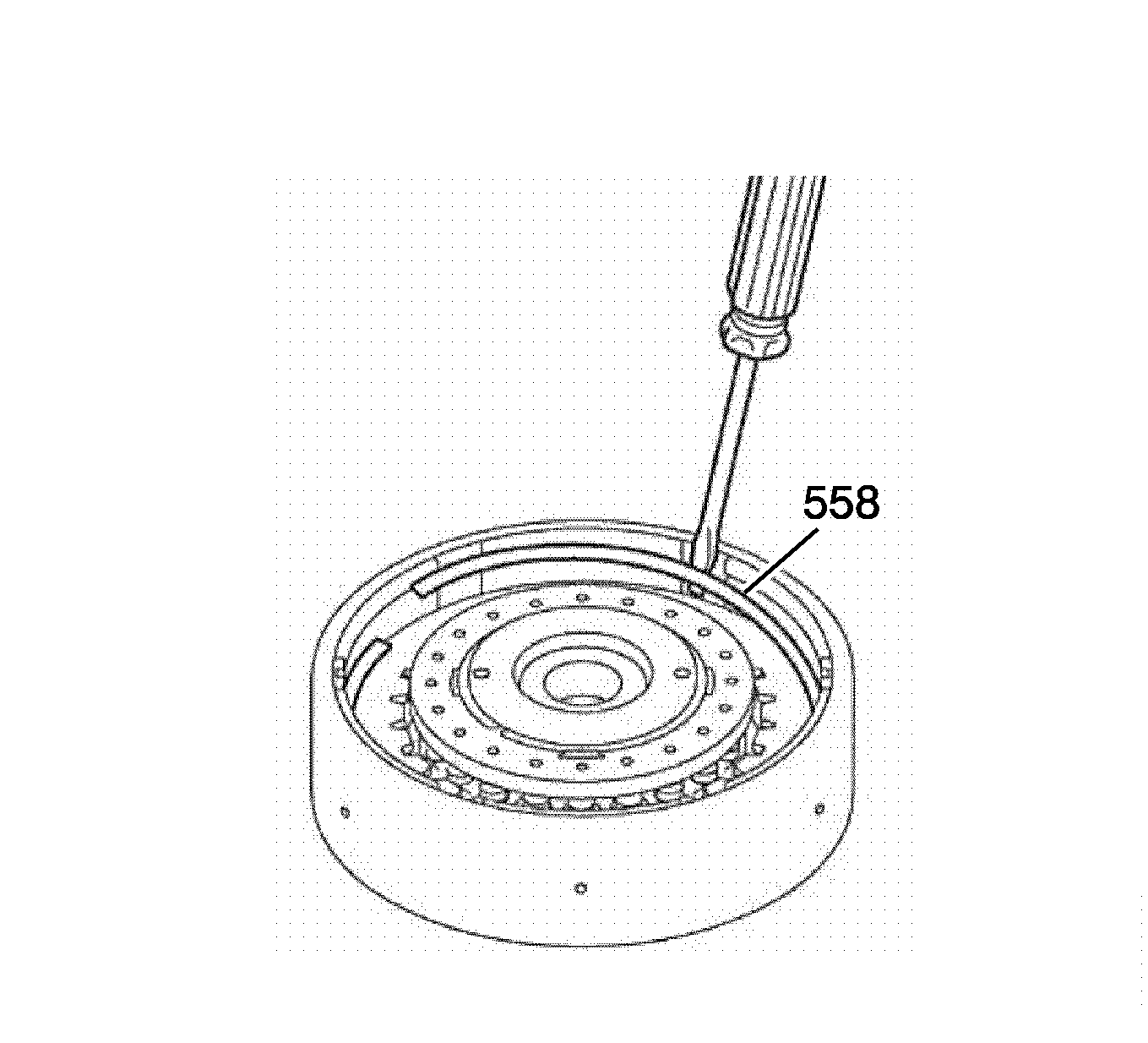
- Remove the reverse gear clutch plate retaining ring (558).
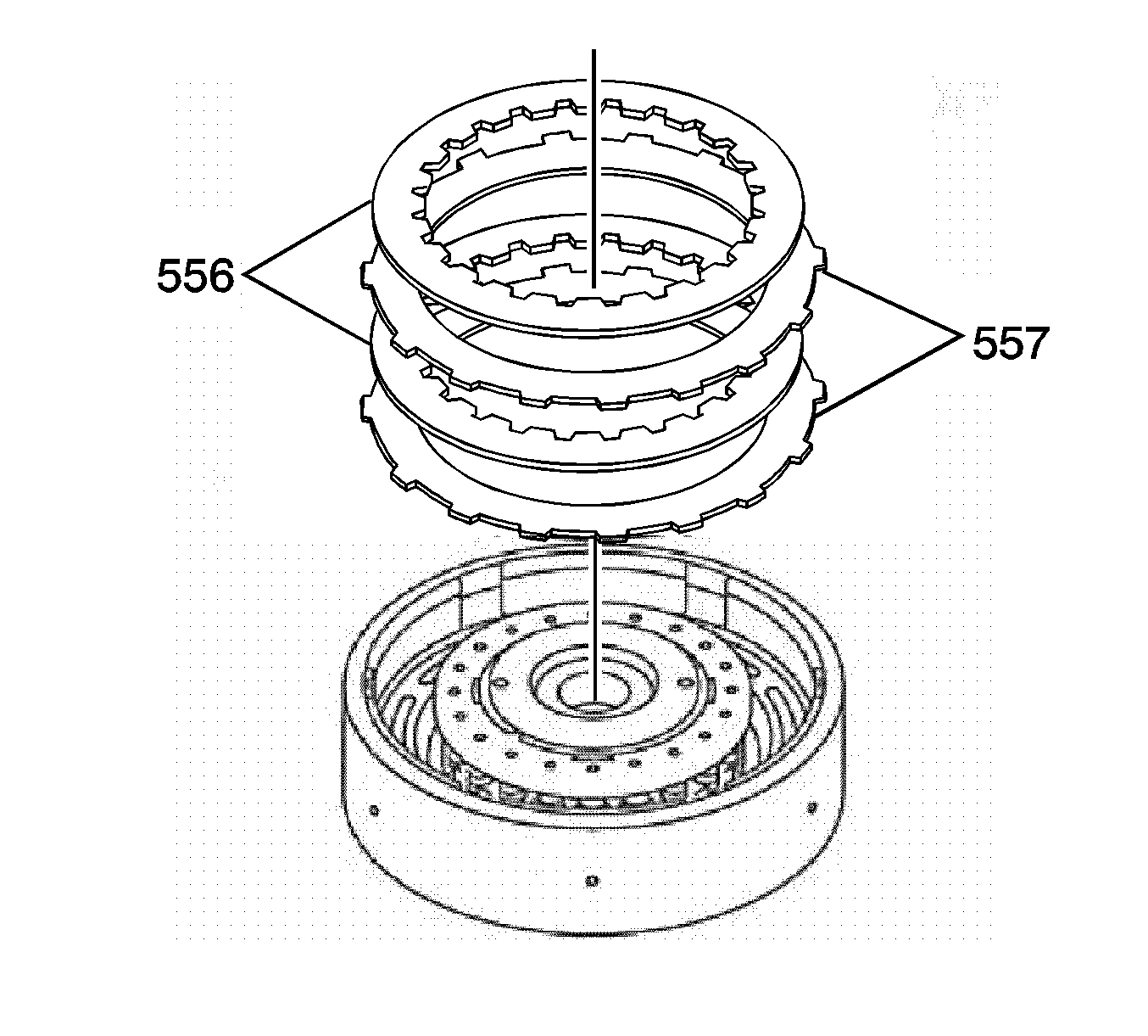
- Remove the reverse gear clutch plate assembly-steel (557) and reverse gear clutch plate assembly-fiber (556).
- Inspect the sliding surface of the discs and plates are not worn or burnt. If necessarey, replace them.
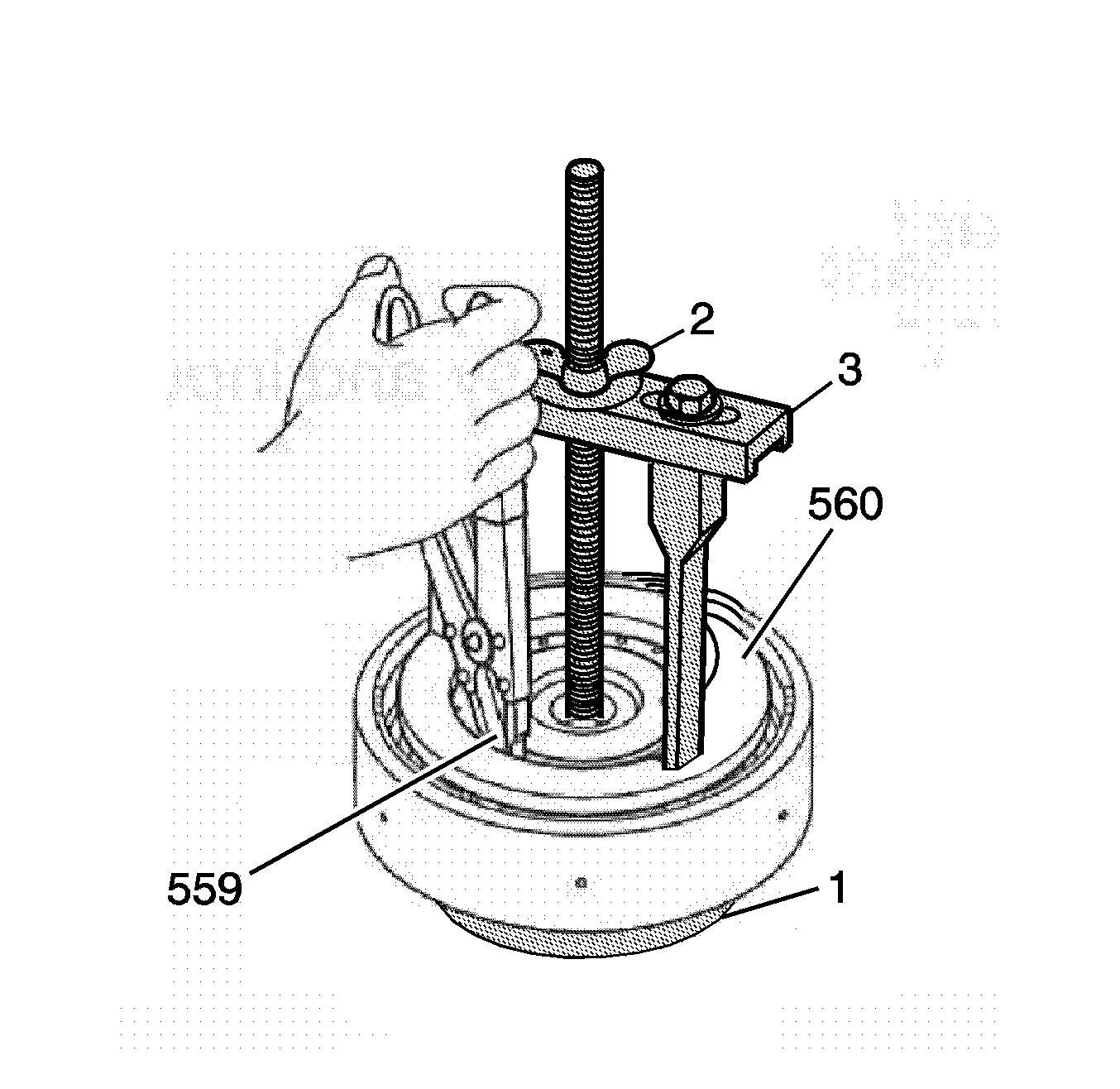
- Using the bridge and legs of the J 45124 (3) with the forcing screw of the J 23327 (2) and J 21420-2 (1) plate, which is part of J 23327 , compress the reverse gear clutch spring (560) until the reverse gear clutch spring retaining ring (559) is accessible.
- Remove the reverse gear clutch spring retaining ring (559).
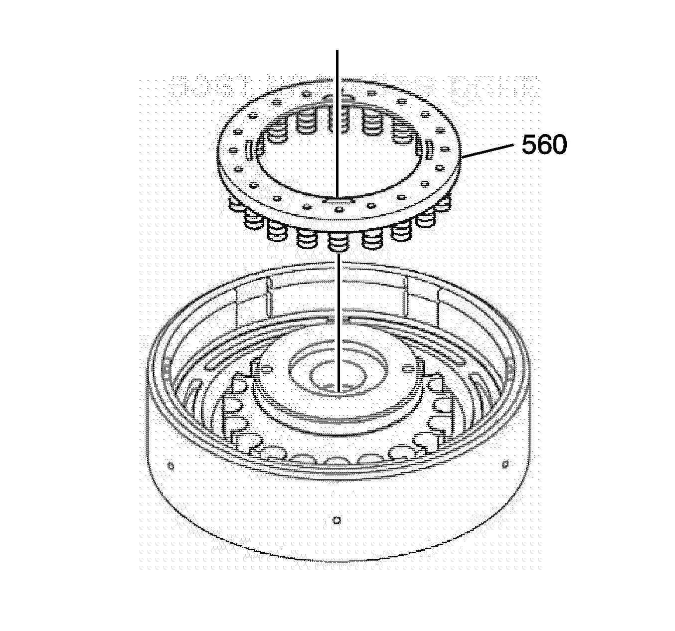
- Remove the reverse gear clutch spring (560).
- Inspect the springs for any damage.
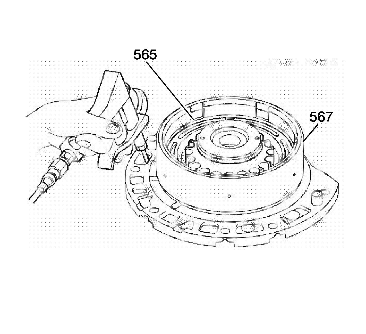
- Install the reverse gear clutch drum (567) onto the fluid pump.
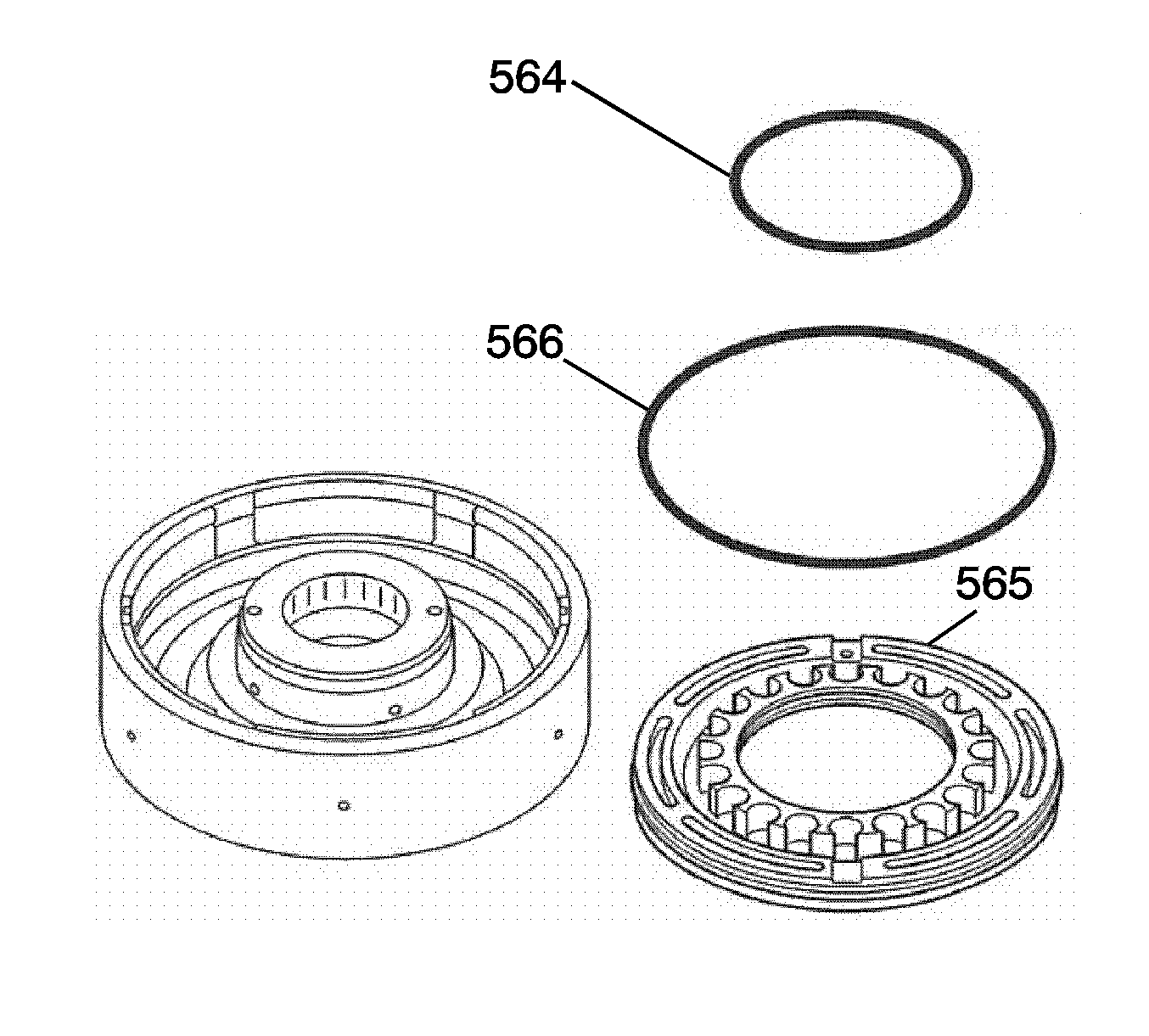
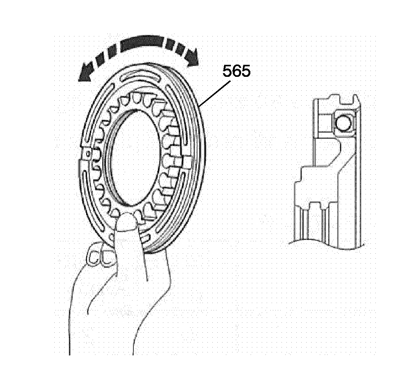
- While pushing the reverse gear clutch piston (565) by hand, apply compressed air 392 KPa (56 psi) into the fluid passage as shown in the figure and remove the reverse gear clutch piston (565).
- Remove the reverse gear clutch piston inner and outer seals (564, 566) from the reverse gear clutch piston (565).
- Inspect the check ball is free by shaking the reverse gear clutch piston (565).
Important: Prepare NEW clutch discs by soaking them at least 2 hours in ATF.
Important: Be careful not to damage the seal rings in the fluid pump.
