Removal Procedure

- Seal off the fluid reservoir (1).
| • | Disconnect the feed line (2) from the clutch master cylinder. |
| • | Collect escaping brake fluid. |
| • | Seal the brake fluid reservoir with the plug. |
| • | Top up brake fluid reservoir to the "MAX" mark. |

- Remove the battery tray. Refer to
Battery Tray Replacement
.
- Place compensation tank for coolant to one side.
Reposition the compensation tank from the support.
- Remove the automatic brake system (ABS) module.
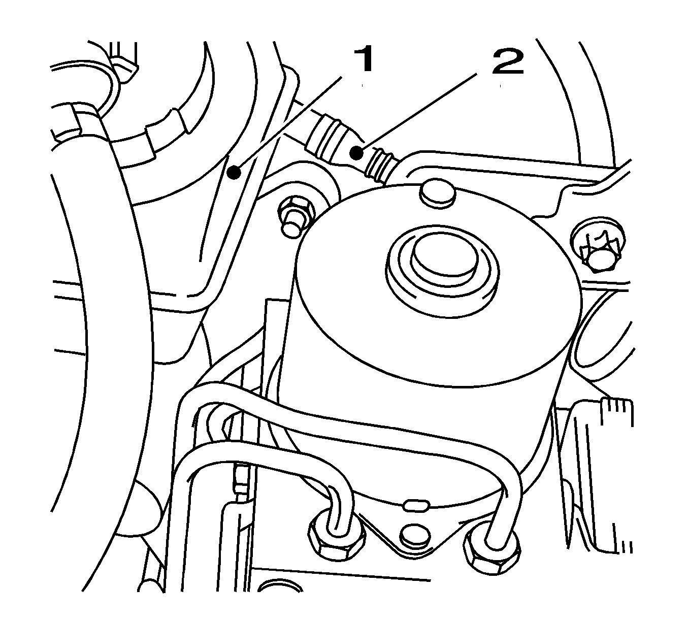
| • | Remove the ABS module at the top (1). |
| - | Remove the 2 bolts (2). |
| - | Disconnect the lead from the bracket. |
| • | Disconnect the ABS module at the bottom. |

- Remove the retaining clamp (1) on the clutch master cylinder.
| • | Carefully push the ABS module to one side. |
| • | Release the retaining clamp using a screwdriver (2). |

- Release the pressure line for the clutch actuator with damper from the clutch master cylinder.
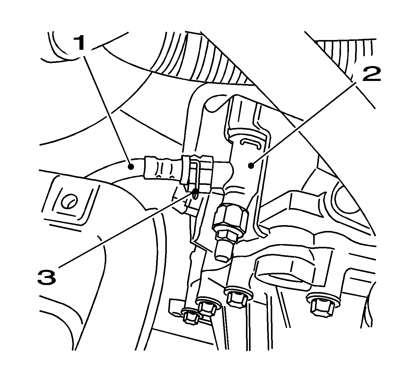
- Disconnect the pressure line for clutch actuator (1) from bracket (2) on battery carrier bracket.

- Remove the pressure line (1) from central release.
| • | Disconnect the retaining clamp (3) on the central release connector (2) with a screwdriver. |
| • | Remove the retaining clamp. |
| • | Remove the pressure line from the central release connector. |

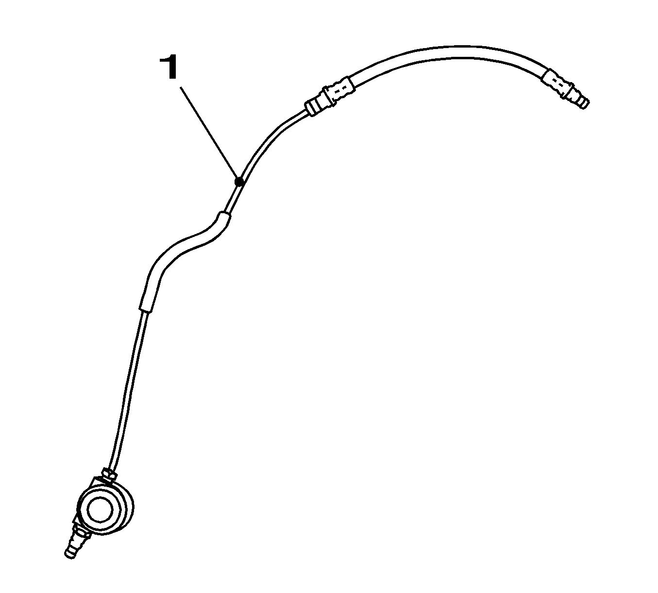
- Remove the clutch actuator pressure line (1).

Important: The O-ring may not remain in the central release connector.
- Inspect the O-ring (1) on the pressure line (2).
Installation Procedure

- Insert the clutch actuator pressure line (1) in the engine compartment.

- Insert the retaining clamp (3).
Bend the retaining clamp together slightly and insert in central release connector (2).
Important: The pressure line must audibly engage.
- Install the pressure line (1) to the central release connector on the clutch housing.

- Install the pressure line for clutch actuator (1) into bracket (2) on battery carrier bracket.

Important: The pressure line must audibly engage.
- Install the pressure line in clutch slave cylinder.
| • | Bend retaining clamp (1) together slightly. |
| • | Carefully push the ABS module to reposition. |
| • | Install the retaining clamp to the clutch master cylinder. |
| • | Push the pressure line into the clutch master cylinder. |
Notice: Refer to Fastener Notice in the Preface section.

- Install the ABS module.
| • | Install the ABS module at the base. |
Tighten
Tighten the bolt (3) to 20 N·m (15 lb ft).
| • | Install the ABS module bracket at the top (1). |
Tighten
Tighten the 2 bolts (2) to 20 N·m (15 lb ft).
| • | Connect the lead into the bracket. |

- Install the surge tank for coolant.
Connect the surge tank to bracket.
- Install the battery tray. Refer to
Battery Tray Replacement
.
- Attach the feed line (2) for the clutch master cylinder.
Connect the feed line for clutch master cylinder to brake fluid reservoir (1).
- For reprogramming procedures, refer to
Control Module References
.
- Bleed the hydraulic clutch. Refer to
Hydraulic Clutch Bleeding
.


