Special Tools
KM-962-A
/KM-962-10 Tester
Removal Procedure

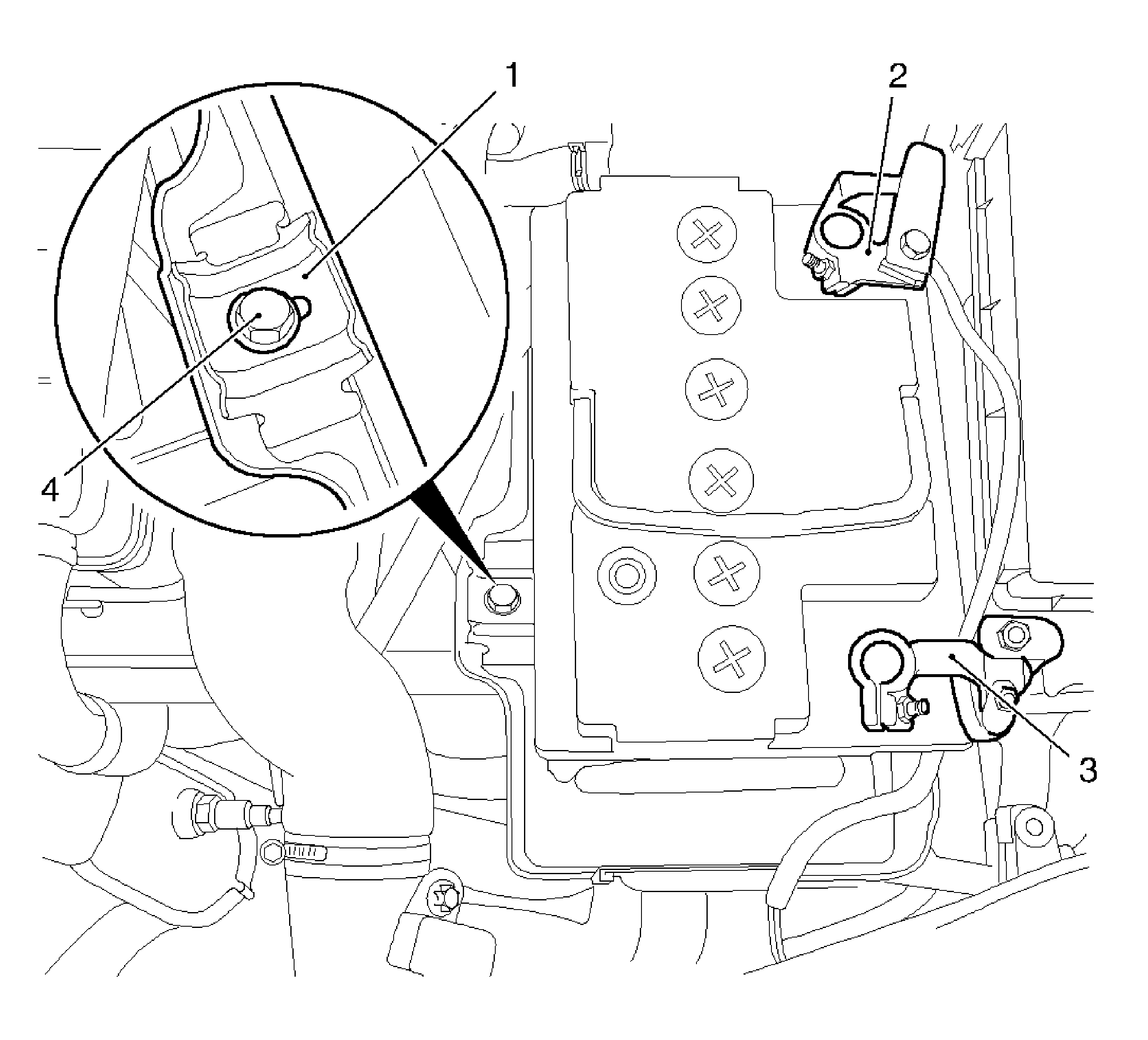
- Remove the battery.
| • | Disconnect the negative cable (2) from the battery. |
| • | Disconnect the positive cable (3) from the battery. |
| • | Remove the bracket (1). |

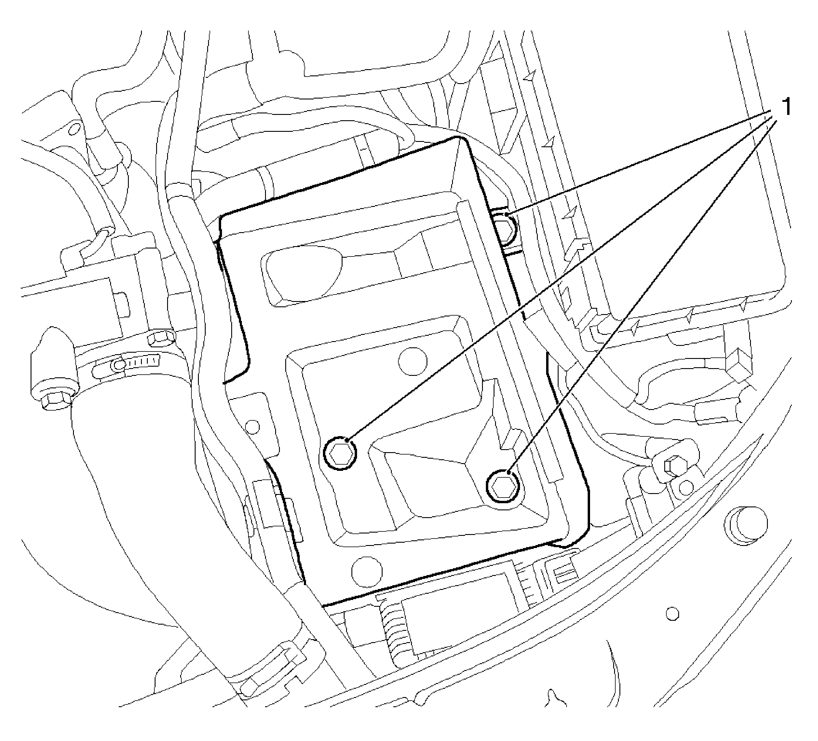
- Remove the battery tray.
| • | Remove the 3 bolts (1). |

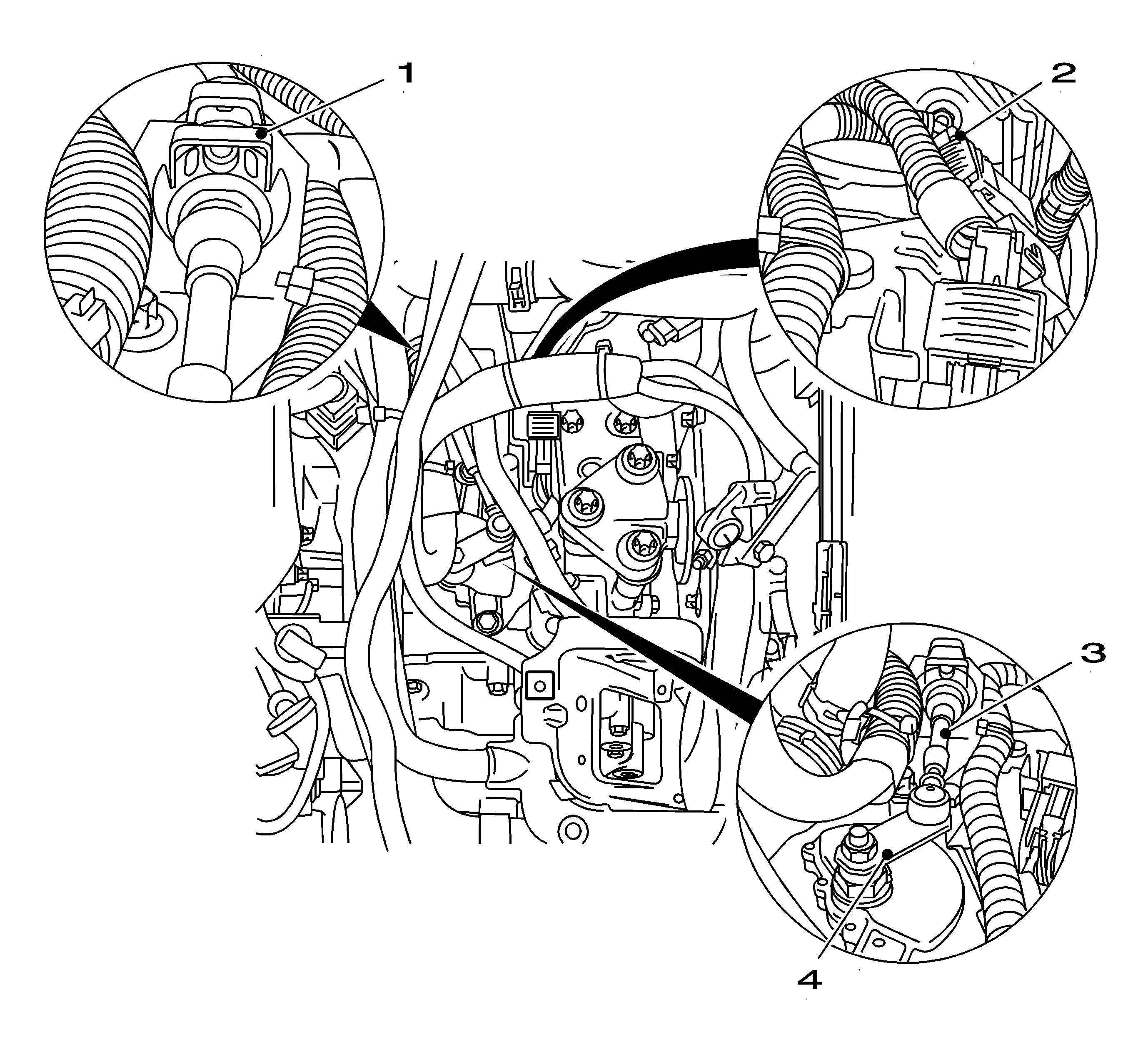
- Remove the selector lever cable (3).
| • | Remove the selector cable from selector lever (4). |
| • | Release the selector lever cable from the counterhold on the transmission. |
| • | Open the retaining clamp (1) with a screwdriver. |
- Disconnect wiring harness plug of the selector lever position switch (2).
Open the locking shackle.
- Install
KM-962-A
(5).
| • | Connect to the wiring harness plug of the selector lever position switch. |
| • | Connect to the battery with
KM-962-A
(1). |
Important: The light diodes corresponding to the markings on the insert module must light up for the selector lever position "N".
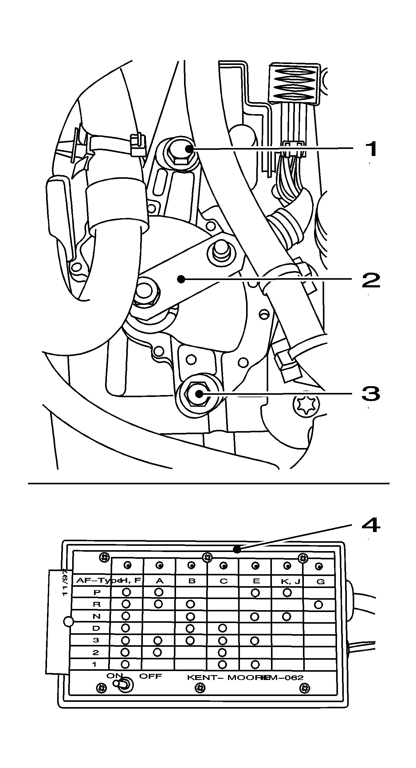
- Inspect the setting of the selector lever position switch.
| • | Move the selector lever to the neutral position |
| • | Turn the selector lever (3) clockwise as far as the stop. |
| • | Twist back 2 notch positions ("P", "R", "N"). |
Important: Until all the light diodes corresponding to selector lever position "N" light up.
- Adjust the selector lever position switch, if necessary.
| • | Release the 2 nuts (2 and 4). |
| • | Twist the selector lever position switch. |
Installation Procedure
Notice: Refer to Fastener Notice in the Preface section.

- Fasten the selector lever position switch.
Tighten
Tighten the 2 bolts (1, 3) to 25 N·m (18 lb ft).
- Inspect the setting of the selector lever position switch.
Important: The light diodes corresponding to the markings on the insert module must flash for each individual gear. Use plug-in check-display (4) for "AF TYPE" (arrow).
- Shift through all the gears one after the other on the selector lever (2).

- Connect and lock the selector lever position switch wiring harness plug (2).
| • | Disconnect
KM-962-A
from the selector lever position switch wiring harness plug. |
Important: Ensure it is correctly engaged.
- Install the selector cable (3).
| • | Install the selector cable to the selector lever (4). |
| • | Connect the selector cable into the counterhold on the transmission. |
| • | Install the retaining clamp (1). |

- Install the battery tray.
Fasten the cable tie.
Tighten
Tighten the 3 bolts to 10 N·m (89 lb in).

- Install the battery.
| • | Install the bracket (1). |
Tighten
Tighten the bolt (4) to 15 N·m (11 lb ft).
| • | Connect the positive cable (3) to the battery. |
| • | Connect the negative cable (2) to the battery. |
- For programming procedures, refer to
Control Module References
.


