Transmission Replacement Transmission Only
Special Tools
Removal Procedure
Important: If the transmission is replaced, the following parts must be transferred:
- Connection piece for clutch actuation.
- Engine damping block bracket.
- Shift Bowden cable bracket.
- Remove the battery tray. Refer to
Battery Tray Replacement
- Place a drain pan underneath.
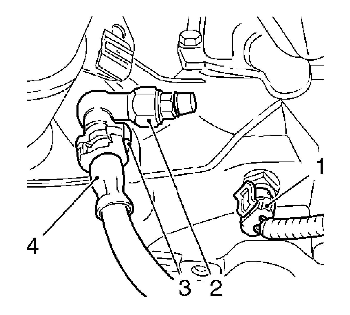
- Disconnect the wiring harness plug, backup lamp switch (1).
- Remove the clutch pressure hose (4) from the connection piece (2).
| • | Open the retaining clamp (3). |
| • | Remove the clutch pressure hose. |
| • | Close the retaining clamp. |
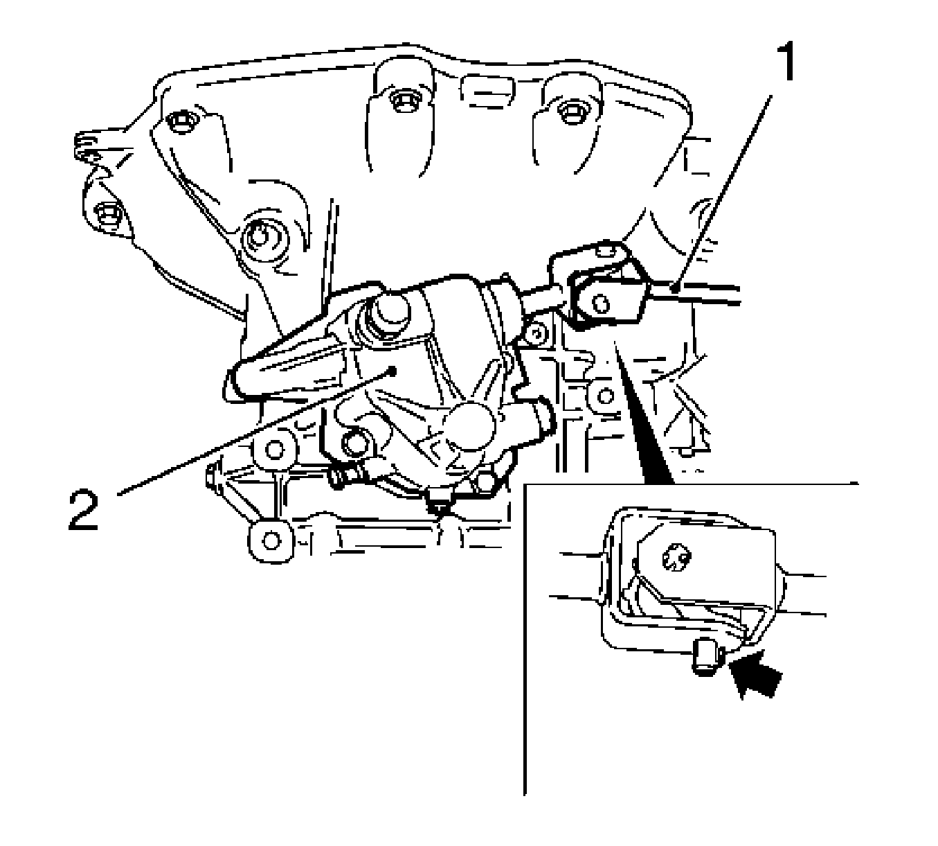
- Remove the selector lever link (1) from the transmission cover (2).
| • | Press in the retaining spring (arrow) of the hollow pin. |
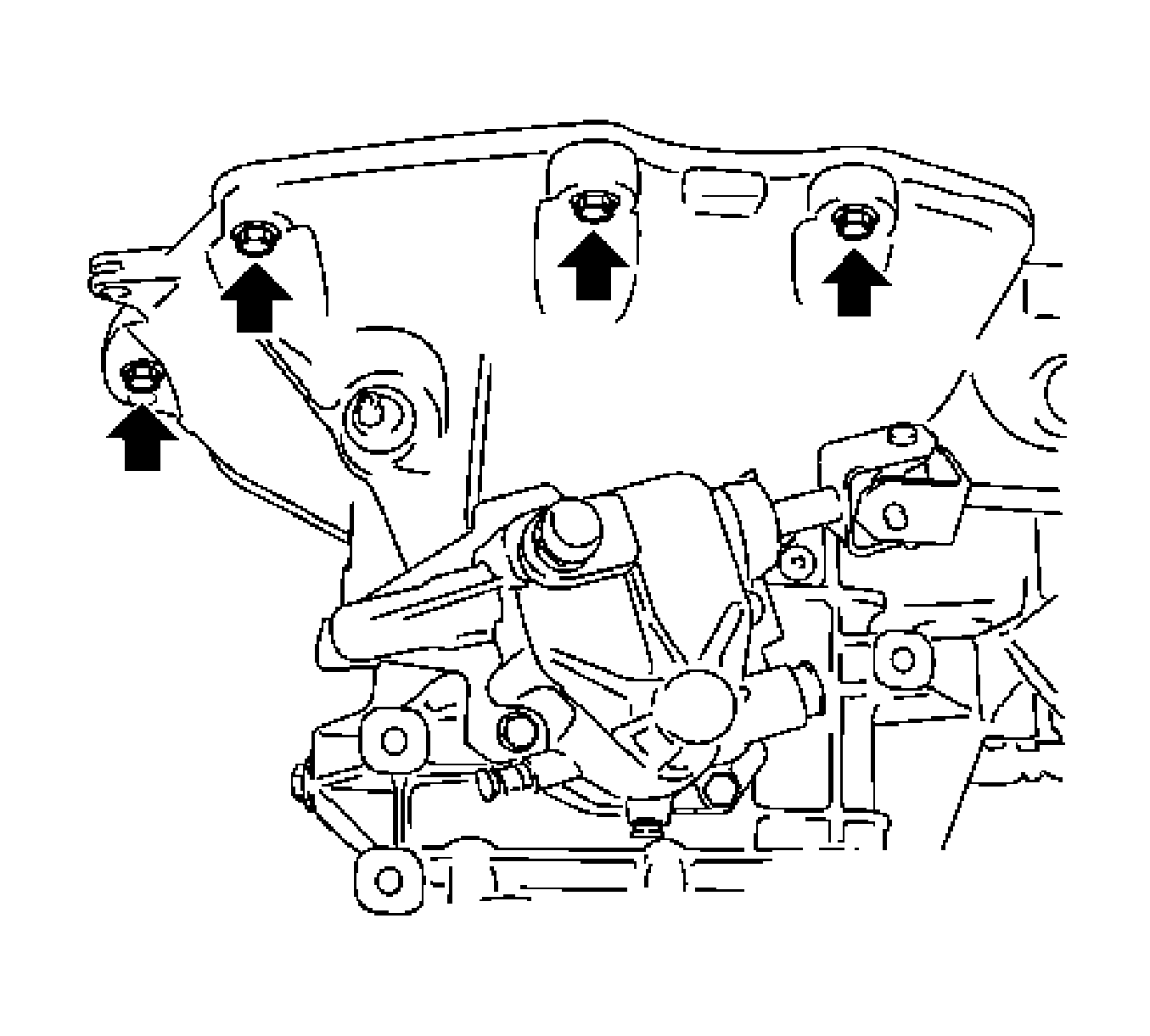
- Release the transmission at the top.
Remove the 4 bolts (arrows).
Notice: Refer to Fastener Notice in the Preface section.

- Attach
KM-6001-A
to the front frame.
| • | Remove the 2 bolts (arrows) for the adjustment rails on
KM-6001-A
(1). |
| | Important: Two journals (2) and (5) must sit flush in the guide holes of the front frame.
|
Tighten
Tighten the 2 bolts for the adjustment rails.
| | Important: The guide pins must sit in the support bearings with no play.
|
| • | Adjust the front support bearing (4) until in contact with the guide pin of the front engine damping block. |
| | Important: The guide pins must sit in the support bearings with no play.
|
| • | Adjust the rear support bearing (3) until in contact with the guide pin of the rear engine damping block bracket. |
- Remove the front frame. Refer to
Front Frame Replacement
.
Important: Axle shafts remain in the wheel hubs.
- Remove the 2 axle shafts from the transmission. Refer to
Wheel Drive Shaft Replacement
.
| • | Attach the axle shafts to the vehicle underbody. |
| • | Seal the 2 openings for the 2 axle shafts with a plug. |
Important: Do not damage wiring harnesses and attaching parts.
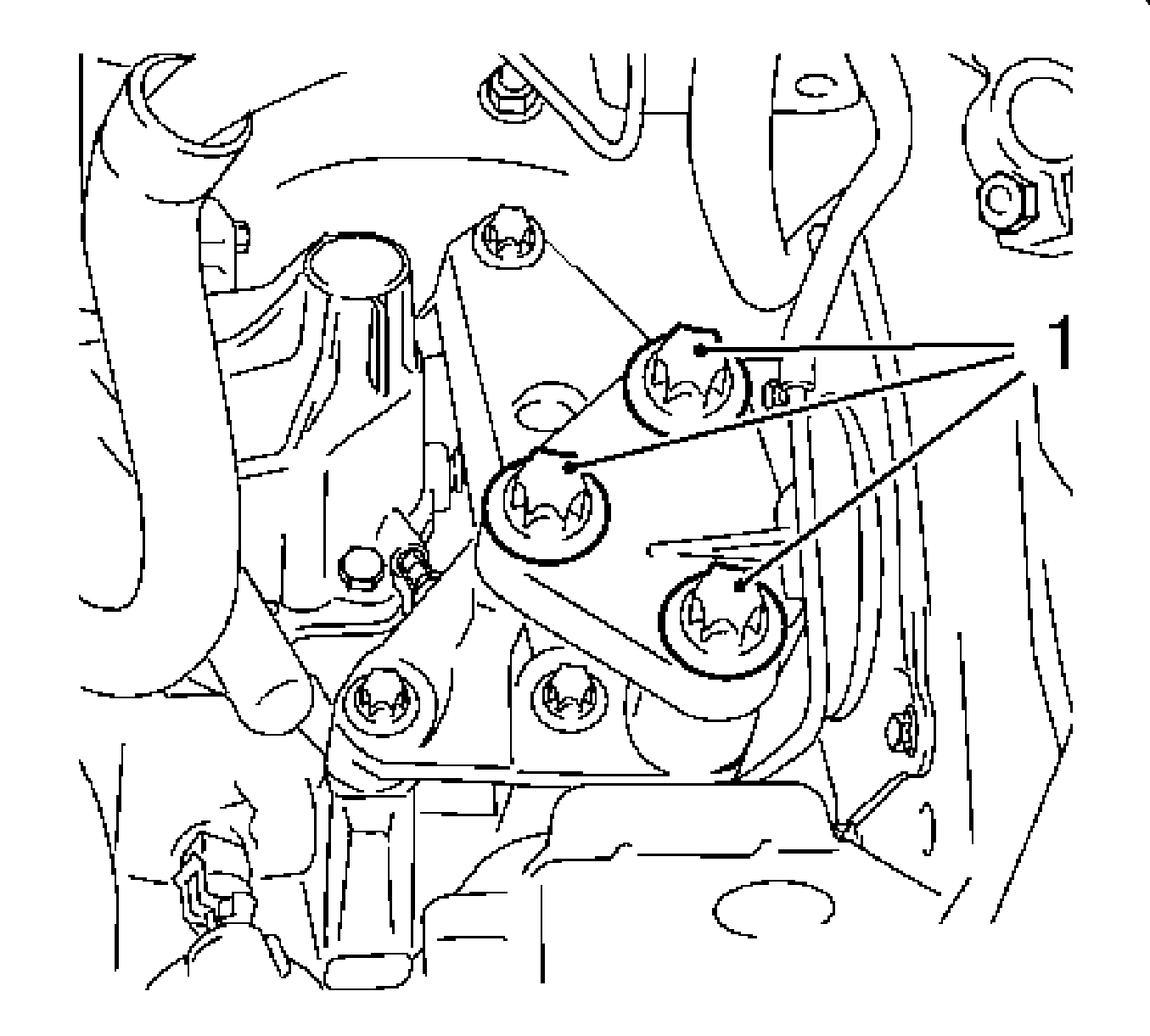
- Remove the transmission from the left engine damping block.
Remove the 3 bolts (1).
- Lower the engine and transmission on the left-hand side.
Use
MKM-883-1
.
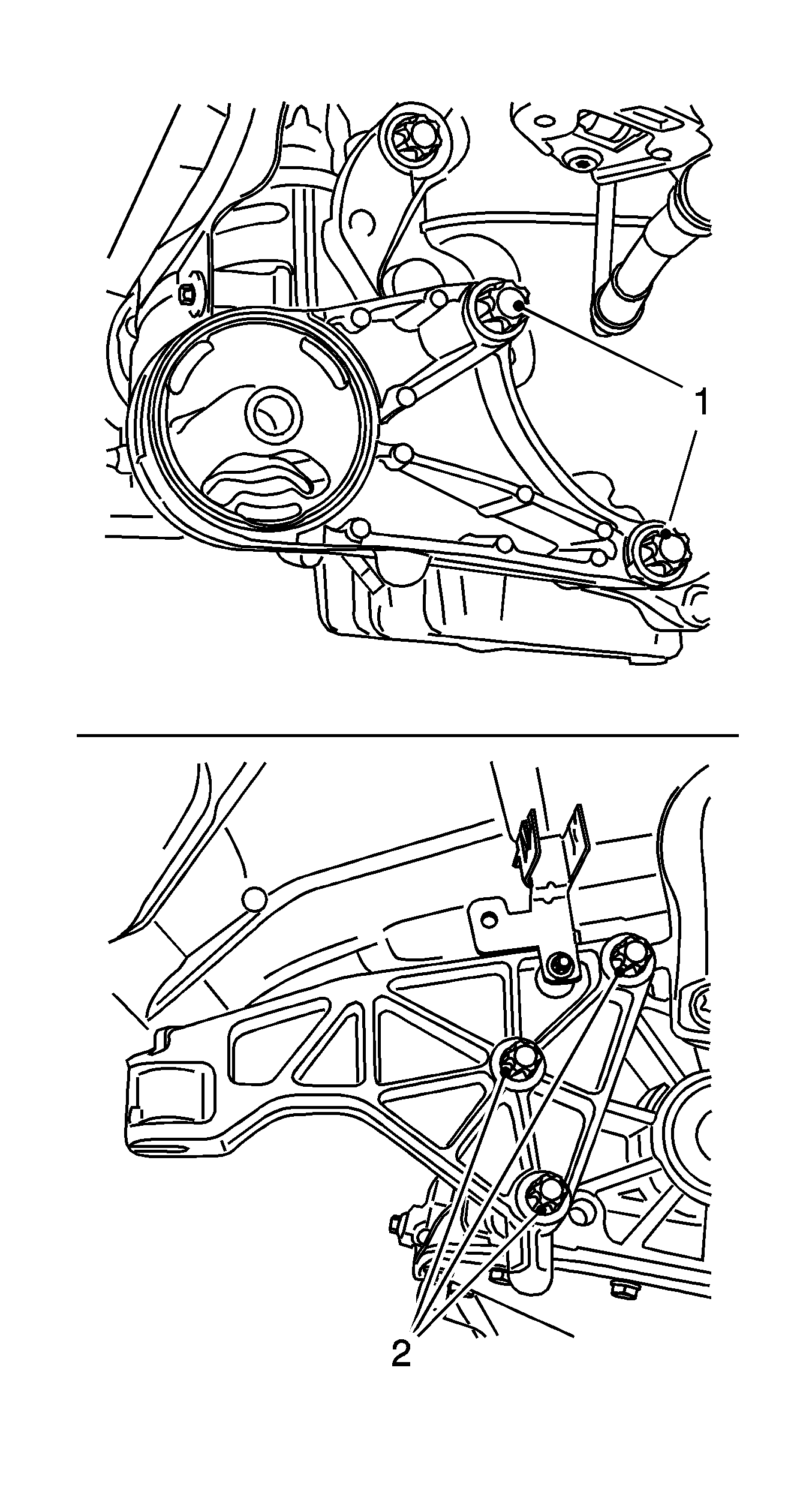
- Remove the front engine damping block bracket.
Remove the 2 bolts (1).
- Remove the rear engine damping block bracket.
Remove the 3 bolts (2).
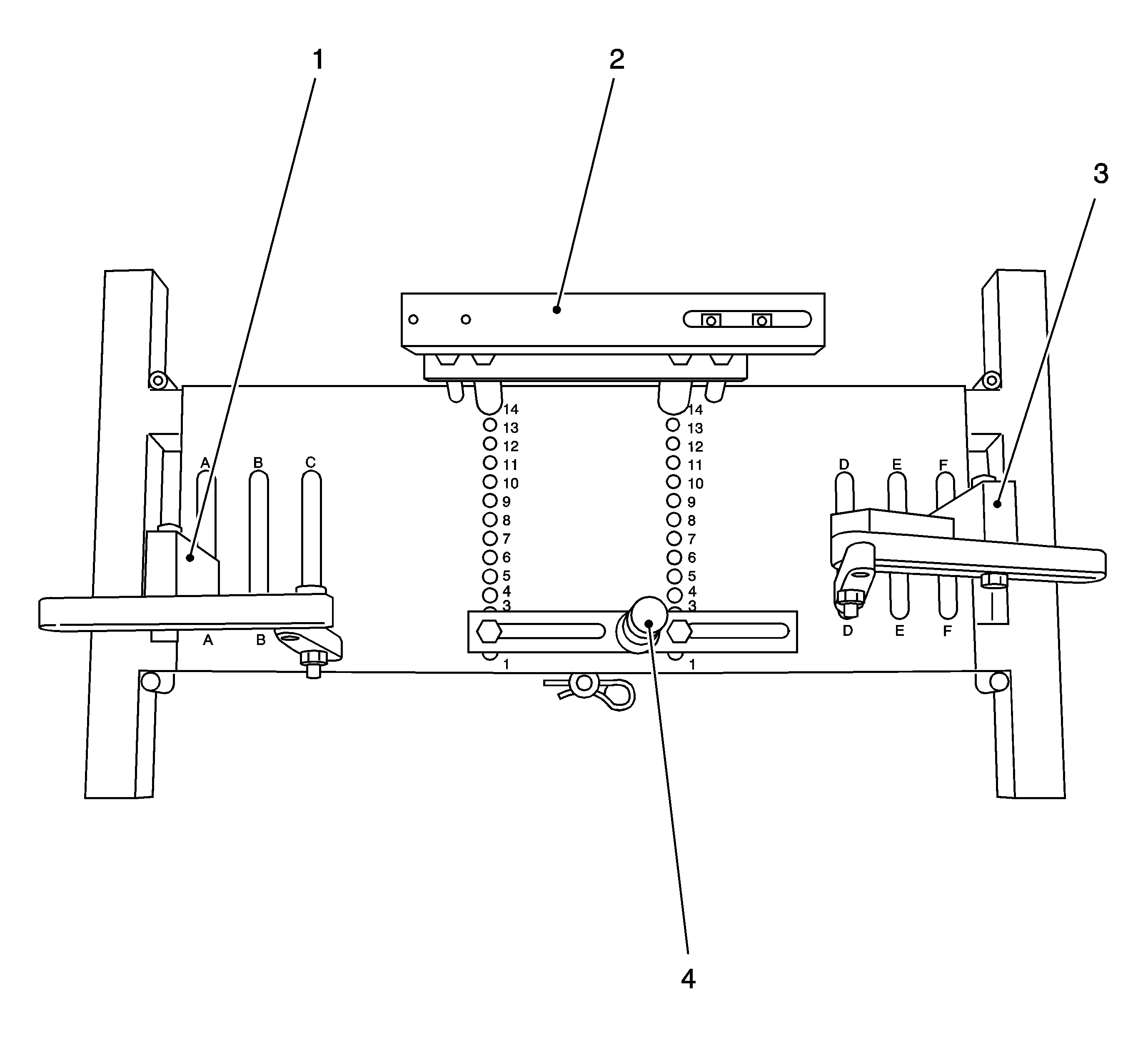
- Place the transmission holder
DT-47648
on
KM-904
and pre-install as shown in the
illustration:
| • | Position on Base Plate-2 |
| • | Designation-Clutch housing support |
| • | Position on Base Plate-14 |
| • | Designation-Transmission housing support |
| • | Position on Base Plate-A |
| • | Designation-Support with rear transmission swivel arm |
| • | Position on Base Plate-F |
| • | Designation-Support with rear transmission swivel arm |
Important: It is essential to follow the manufacturer's instructions for transmission holder
DT-47648
.
Important: Before placing in position, slacken all bolt connections of the swivel arms and supports as far as the base plate. Adjust the supports using the spindles until they are as low as possible.
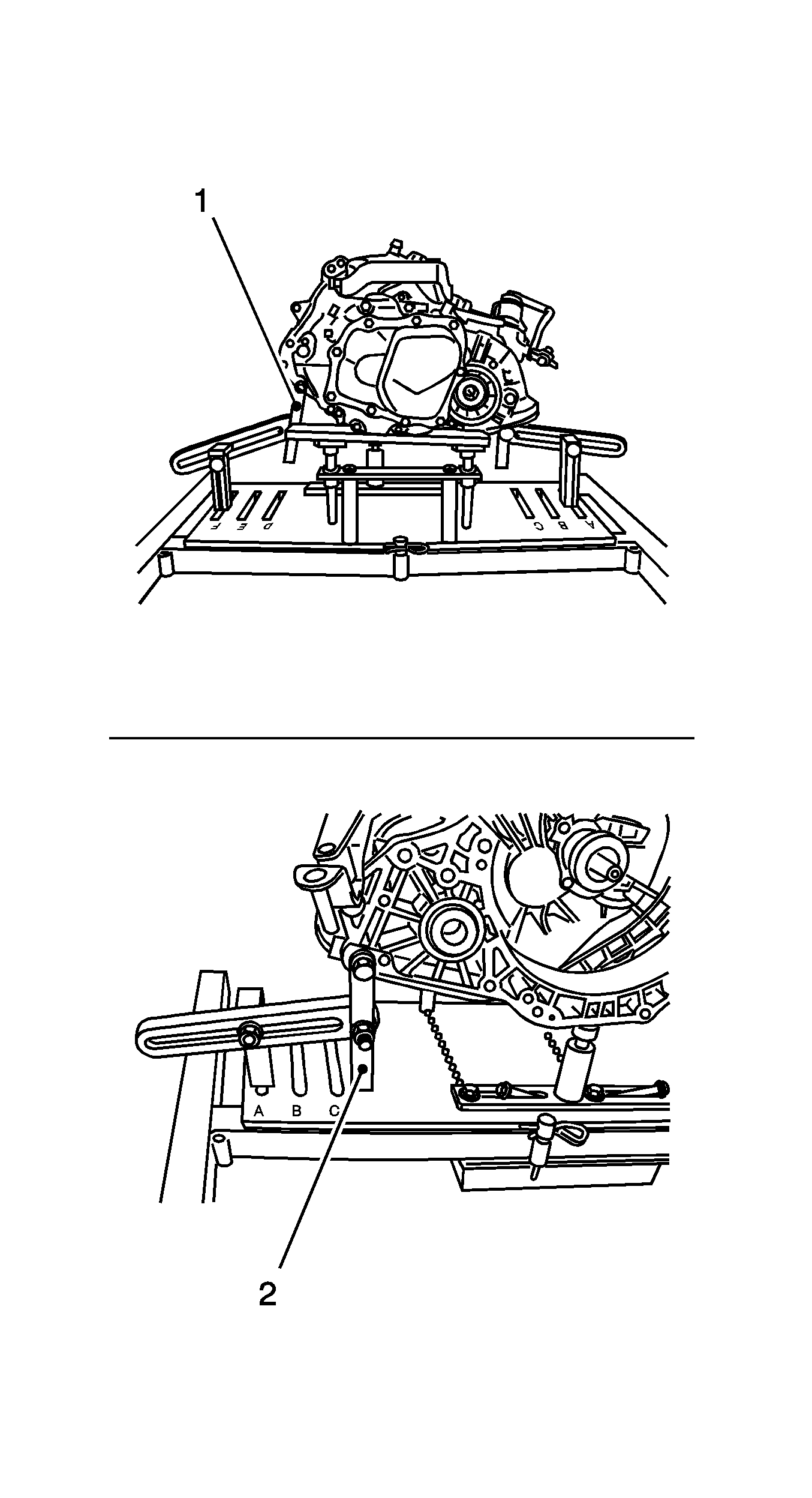
- Attach the transmission holder
DT-47648
to the transmission.
| • | Place the transmission holder
DT-47648
with supports in position under the transmission. |
| • | Tighten the bolt connections of the supports |
| • | Attach the swivel arm (1) and (2) to the transmission. |
| | Important: Align the swivel arms so that as little leverage as possible is created.
|
| • | Tighten the bolt connections of the swivel arms starting from the transmission and going as far as the base plate |

Important: Do not damage attaching parts when putting the transmission down.
- Remove the transmission.
| • | Remove the 3 bolts (2), transmission to oil pan. |
| | Important: Note differing bolt lengths.
|
| • | Remove the 3 bolts (1) and (3), transmission to cylinder block. |
| | Important: Do not damage attaching parts.
|
| • | Pry the transmission away from the engine. |
| • | Carefully lower the transmission with the hydraulic jack and extend the hydraulic jack. |
- With the aid of an assistant, remove the transmission from
DT-47648
.
| • | Put the transmission down carefully. |
Installation Procedure
Notice: Refer to Fastener Notice in the Preface section.
- With the aid of an assistant, attach the transmission to
DT-47648
. Tighten the 2 bolts.
Important: Ensure that no cables and brackets get trapped between the transmission and engine.
Important: Ensure it is seated perfectly.
- Install the transmission with
DT-47648
| • | Raise the transmission and align it. |
| • | Place the transmission so that it is in even contact with the engine. |

- Install the transmission.
Install the wiring harness bracket with the front bolt.
Tighten
| • | Tighten the 3 transmission to cylinder block bolts (1) and (3) to 60 N·m (44 lb ft) . |
| • | Tighten the 2 transmission to oil pan bolts (2) to 40 N·m (30 lb ft) . |
- Remove the transmission holder
DT-47648
from the transmission.
| • | Lower and extend the hydraulic jack. |
Important: Do not damage wiring harnesses and attaching parts.
- Raise the engine and transmission on the left hand side.
Raise with
MKM-883-1
.

Important: Do not tighten bolts yet.
- Attach the transmission to left hand engine damping block.
Tighten
Tighten the 3 bolts (1) to 80 N·m (59 lb ft).

- Install the front engine damping block bracket.
Tighten
Tighten the 2 bolts (1) to 80 N·m (59 lb ft).
- Install the rear engine damping block bracket.
Tighten
Tighten the 3 bolts (2) to 80 N·m (59 lb ft).
- Install the 2 axle shafts to the transmission. Refer to
Wheel Drive Shaft Replacement
.
Important: Do not detach
MKM-883-1
yet.
- Install the front frame. Refer to
Front Frame Replacement
.

- Attach the transmission to left hand engine damping block.
Tighten
Tighten the 3 bolts (1) to 55 N·m (41 lb ft).
- Remove
KM-6001-A
from the front frame.

- Fasten the transmission at the top.
Tighten
Tighten the 4 bolts (arrows) to 60 N·m (44 lb ft).

- Attach the selector lever link (1) to the transmission cover (2).
Insert a new roll pin (arrow).
| • | Coat the roll pin with grease. |
| • | Depress the roll pin until retaining spring engages. |
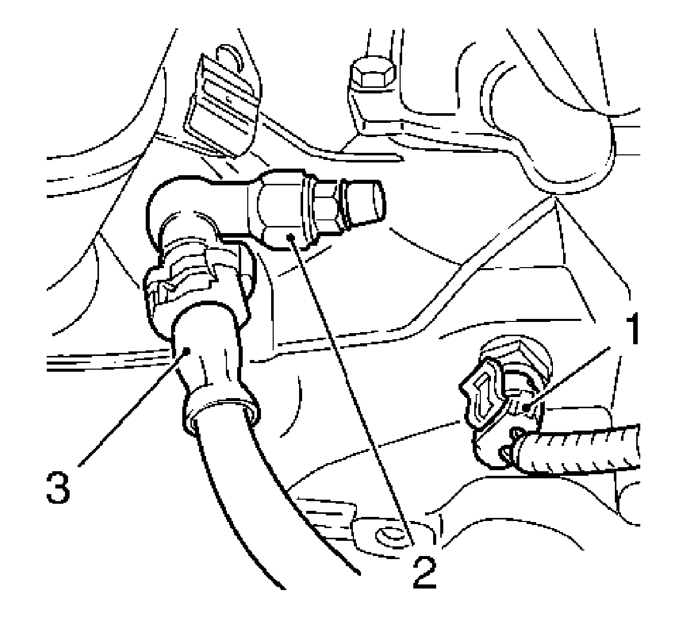
- Connect the wiring harness plug for the reversing lamp switch (1).
Important: The clutch pressure hose must audibly engage.
- Attach the clutch pressure hose (3) to the connection piece (2).
- Inspect for correct transmission fluid level. Refer to
Transmission Fluid Check
.
- Adjust the transmission selector lever link. Refer to
Selector Lever Link Adjustment
.
- Bleed the hydraulic clutch actuation. Refer to
Hydraulic Clutch Bleeding
.
- Install the battery tray. Refer to
Battery Tray Replacement
.
- For reprogramming procedures, refer to
Control Module References
.
.
Transmission Replacement Engine and Transmission
Special Tools
| • | OTC 1726
/ KM-412-31-1/KM-412-31-2 Engine Overhaul Stand |
Removal Procedure
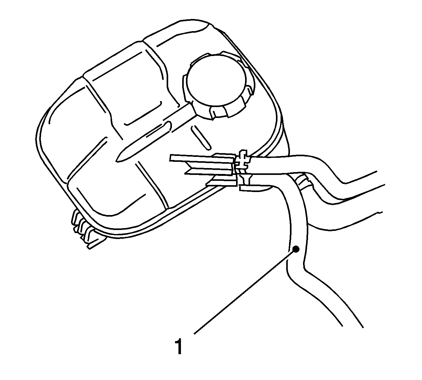
Important: Engine with manual transmission removed.
- Remove the coolant return hose, throttle valve pre-heating (1) from the coolant surge tank.
| • | Unclip from the bracket. |
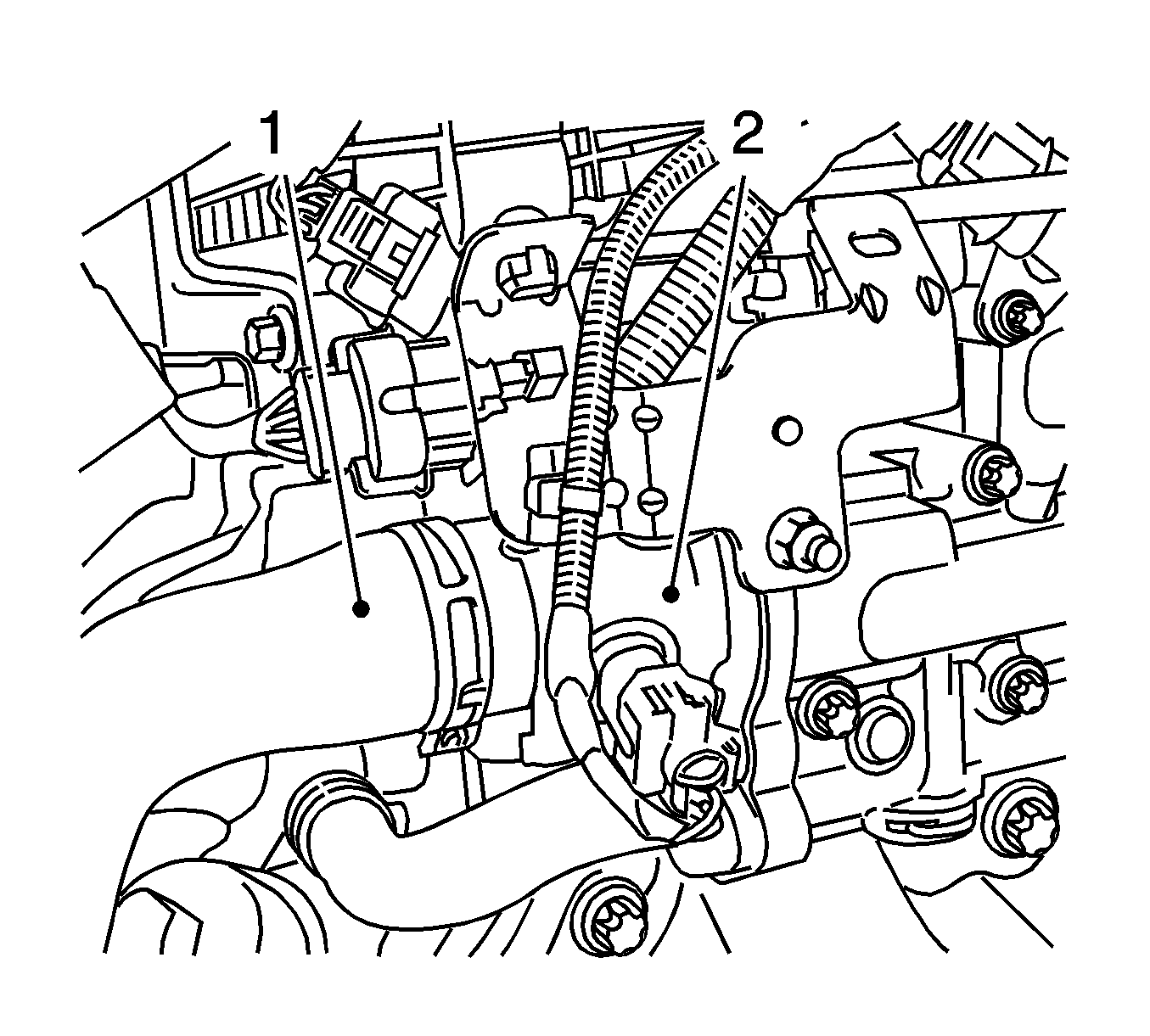
- Remove the upper radiator hose (1) from the thermostat (2).
Release the clamp.
- Remove the lower radiator hose from the coolant pump.
| • | Unclip from the bracket. |

- Remove the refrigerant lines (1) from the air conditioning (A/C) compressor.
Remove the bolt (2).
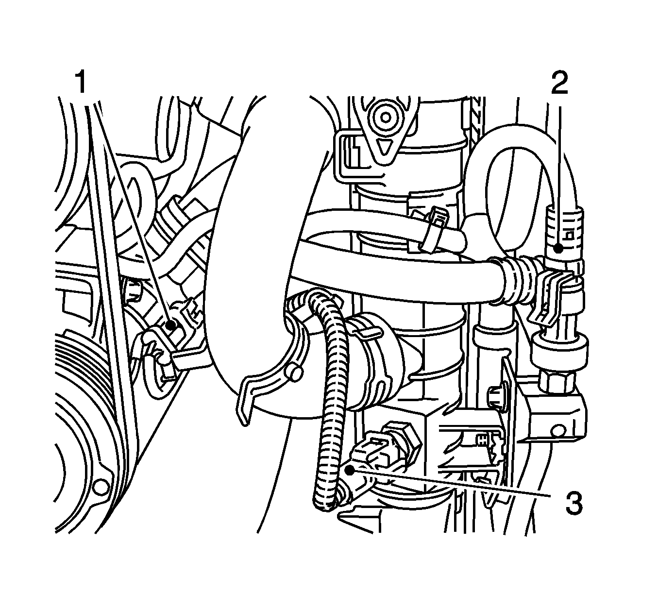
- Disconnect the 3 wiring harness plugs.
| • | Manometric switch, condenser (2) |
| • | Disconnect the wiring harness. |
| • | Temperature sensor, radiator (3) |

- Remove the radiator (1).
Remove from the lower radiator brackets.
- Place the collecting basin underneath.
- Remove the right-hand axle body.
| • | Remove the axle body with
KM-460-B
(1) from the differential gear. |
| • | Seal the opening in differential with the sealing plug. |

- Remove the left-hand axle body.
| • | Remove the axle body with
KM-313
and
KM-6003
(1) from the differential gear. |
| • | Seal the opening in the differential with the sealing plug. |
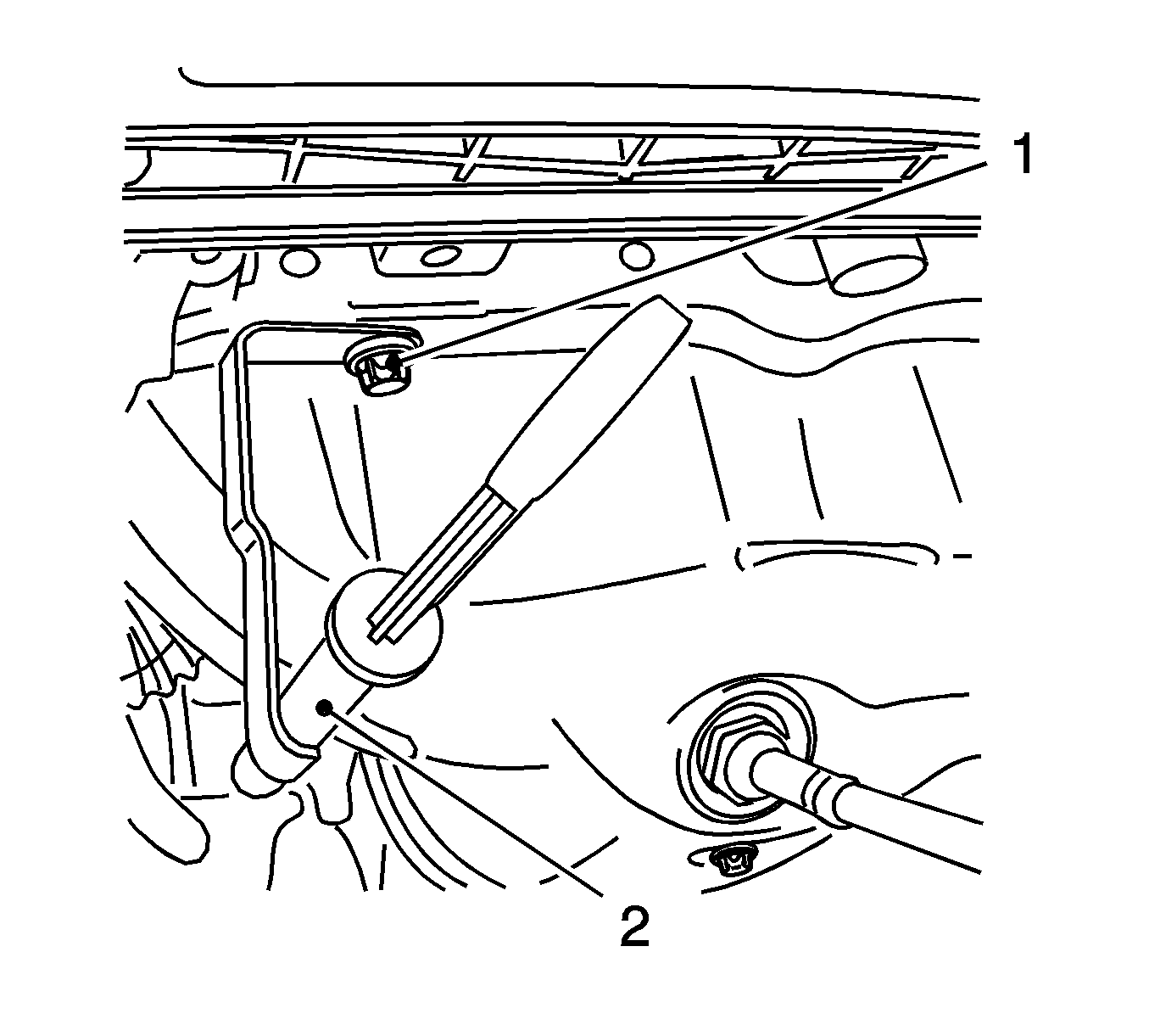
- Remove the oil dipstick guide tube (2).
| • | Remove the oil dipstick guide tube upward. |
- Remove the wiring harness plug of the catalytic converter control oxygen sensor.
| • | Disconnect the wiring harness connector. |
| • | Unclip from the bracket. |
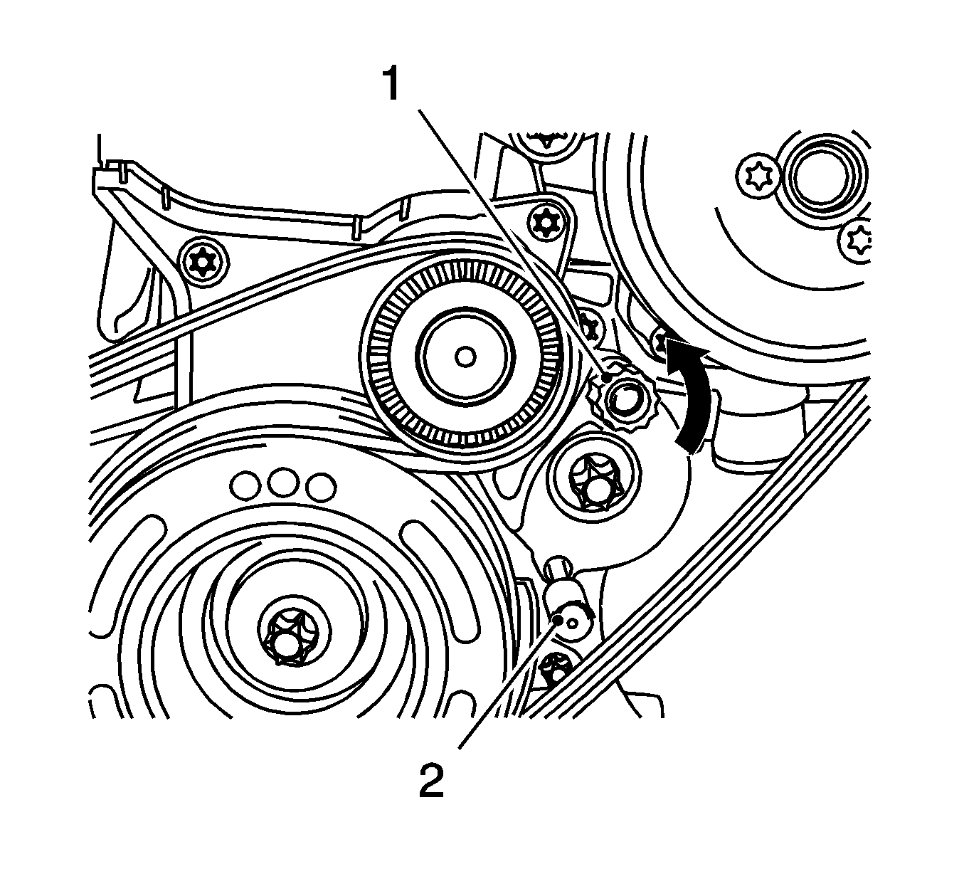
- Remove the ribbed V-belt.
| • | Apply tension to the ribbed V-belt tensioner in the direction of the arrow at the projection (1) and lock with
KM-6349
(2). |
| • | Remove the ribbed-V-belt. |
- Remove the exhaust manifold heat shield.
Remove the 3 bolts.
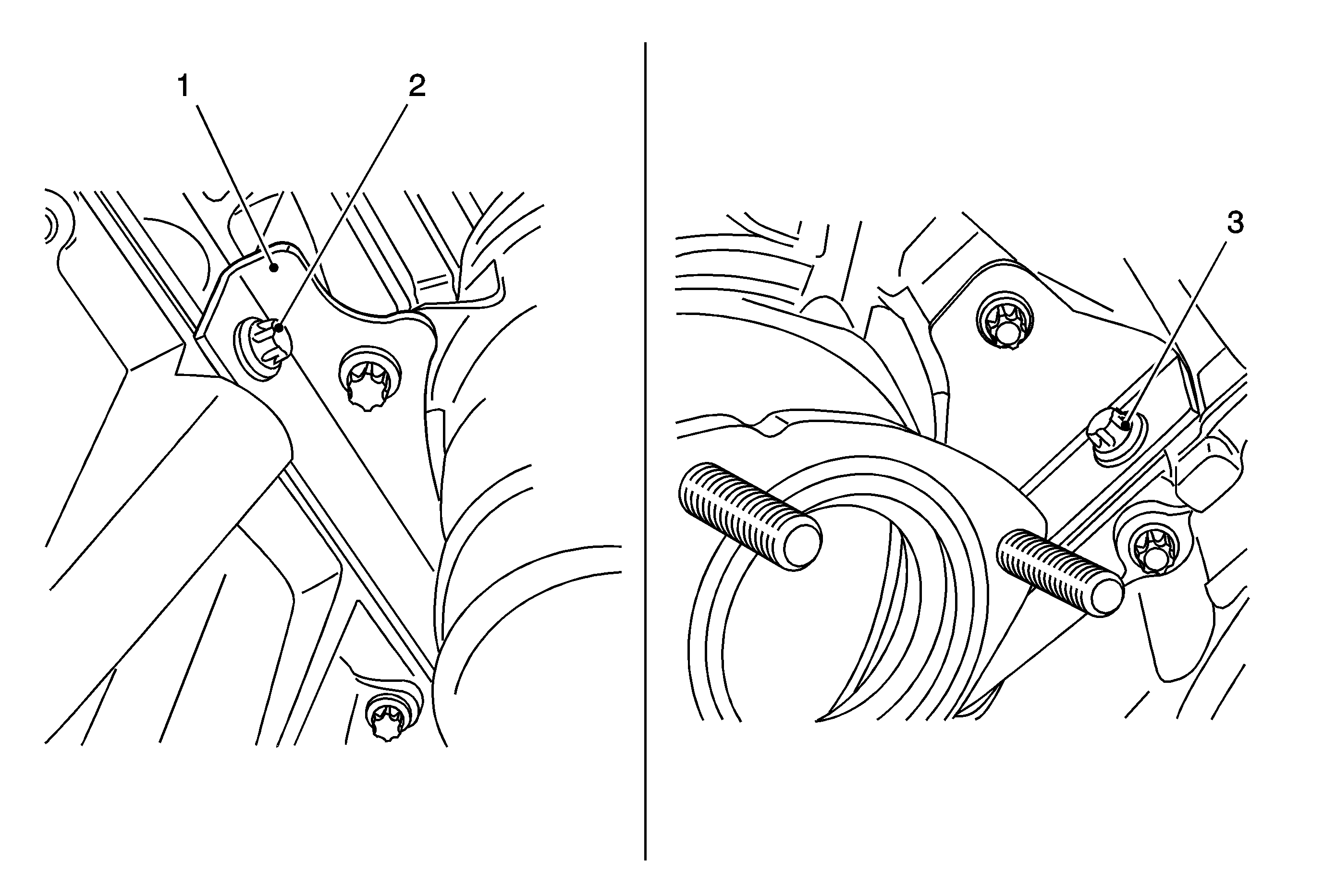
- Remove the bracket for the catalytic converter (1) from the cylinder block.
Remove the 2 bolts (2, 3).
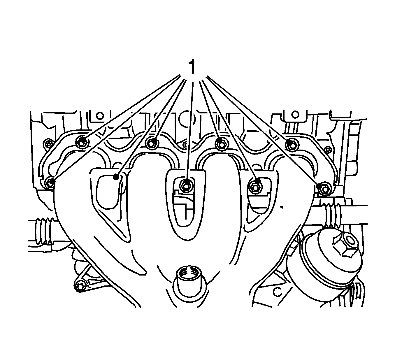
- Remove the exhaust manifold.
Remove the 9 nuts (1).
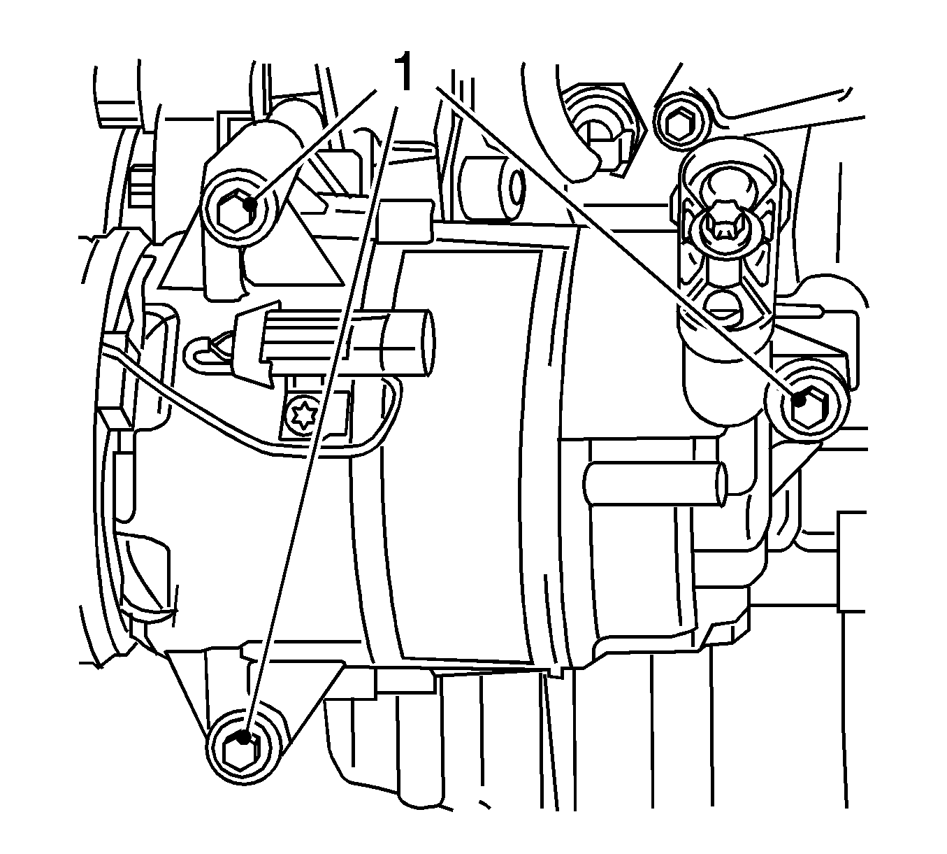
- Remove the compressor.
Remove the 3 bolts (1).
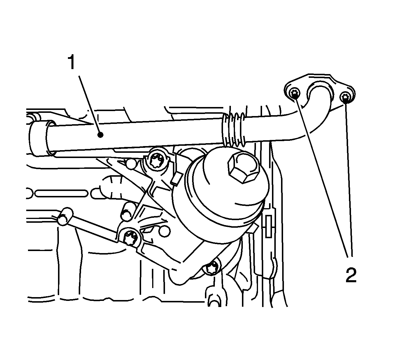
- Remove the coolant pipe (1) between the thermostat housing and the oil filter housing.
| • | Remove the 2 bolts (2). |
| • | Draw out of the oil filter housing. |
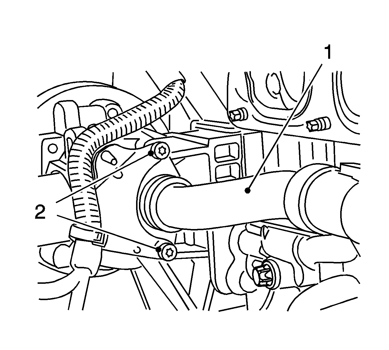
- Remove the coolant pipe (1) from the coolant pump.
| • | Remove the 2 bolts (2). |
| • | Push the coolant pipe into the oil filter housing. |
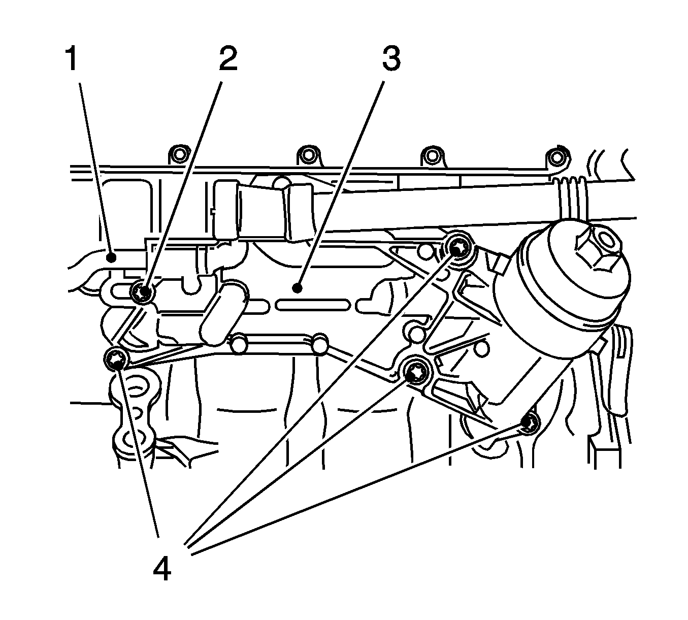
- Remove the oil filter housing (3).
| • | Release the coolant pipe (1) and push into the oil filter housing. |
| • | Remove the 4 bolts (4). |
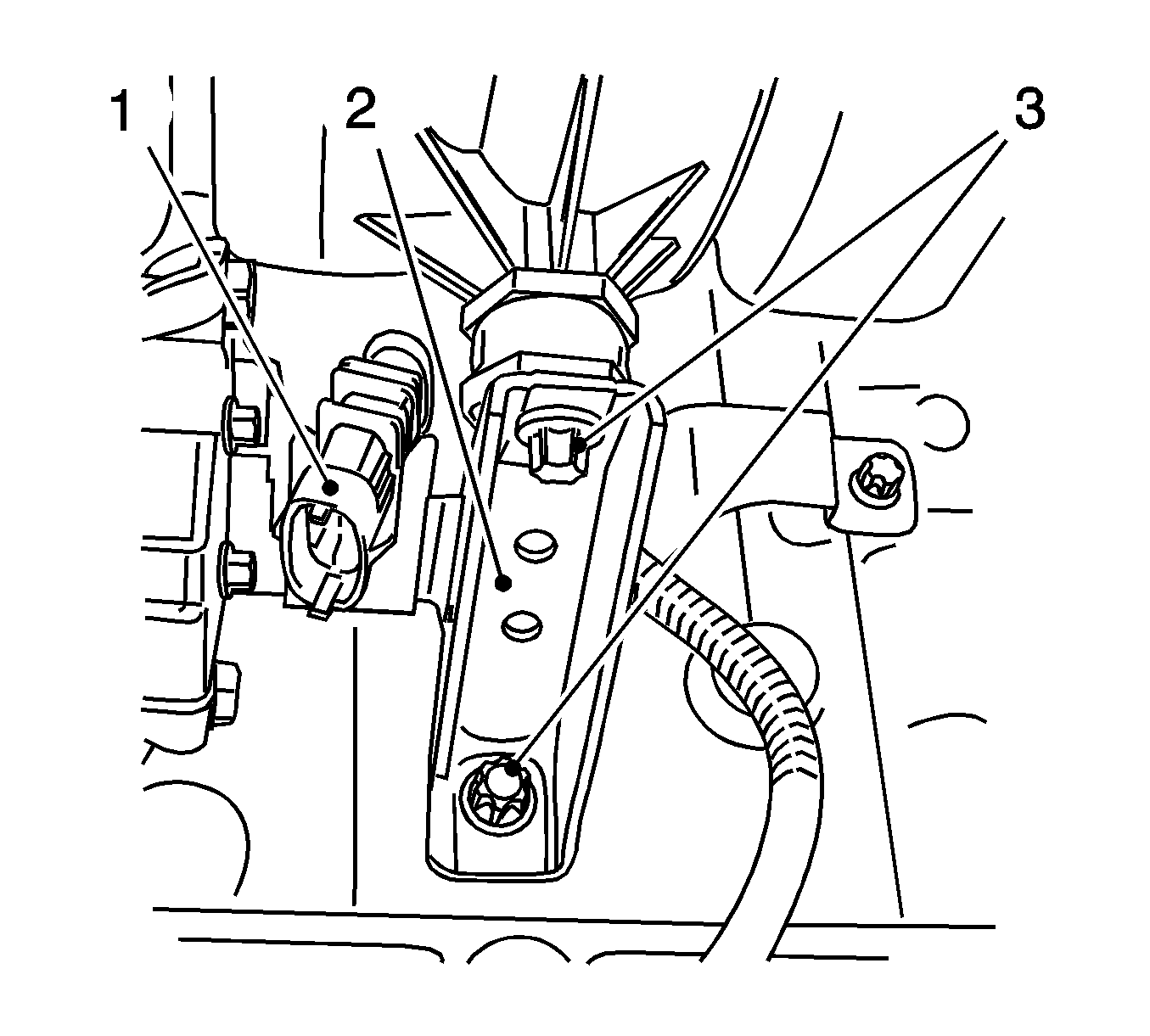
- Remove the intake manifold support (2).
| • | Disconnect the wiring harness plug of the catalytic converter control oxygen sensor. |
| • | Unclip the wiring harness plug (1) from the bracket. |
| • | Remove the 2 bolts (3). |
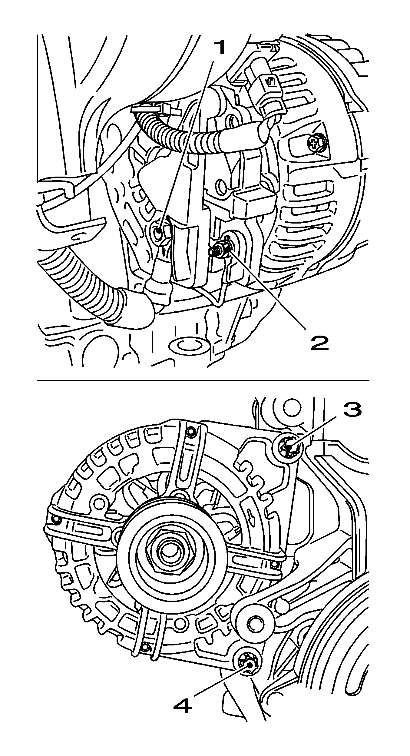
- Disconnect the generator from the power supply.
Remove the 2 nuts (1, 2).
- Remove the generator.
Remove the 2 bolts (3, 4).

- Remove the negative cable (1) from the starter.
Remove the nut.
- Remove the 2 positive cables (2) from the starter.
Remove the 2 nuts.
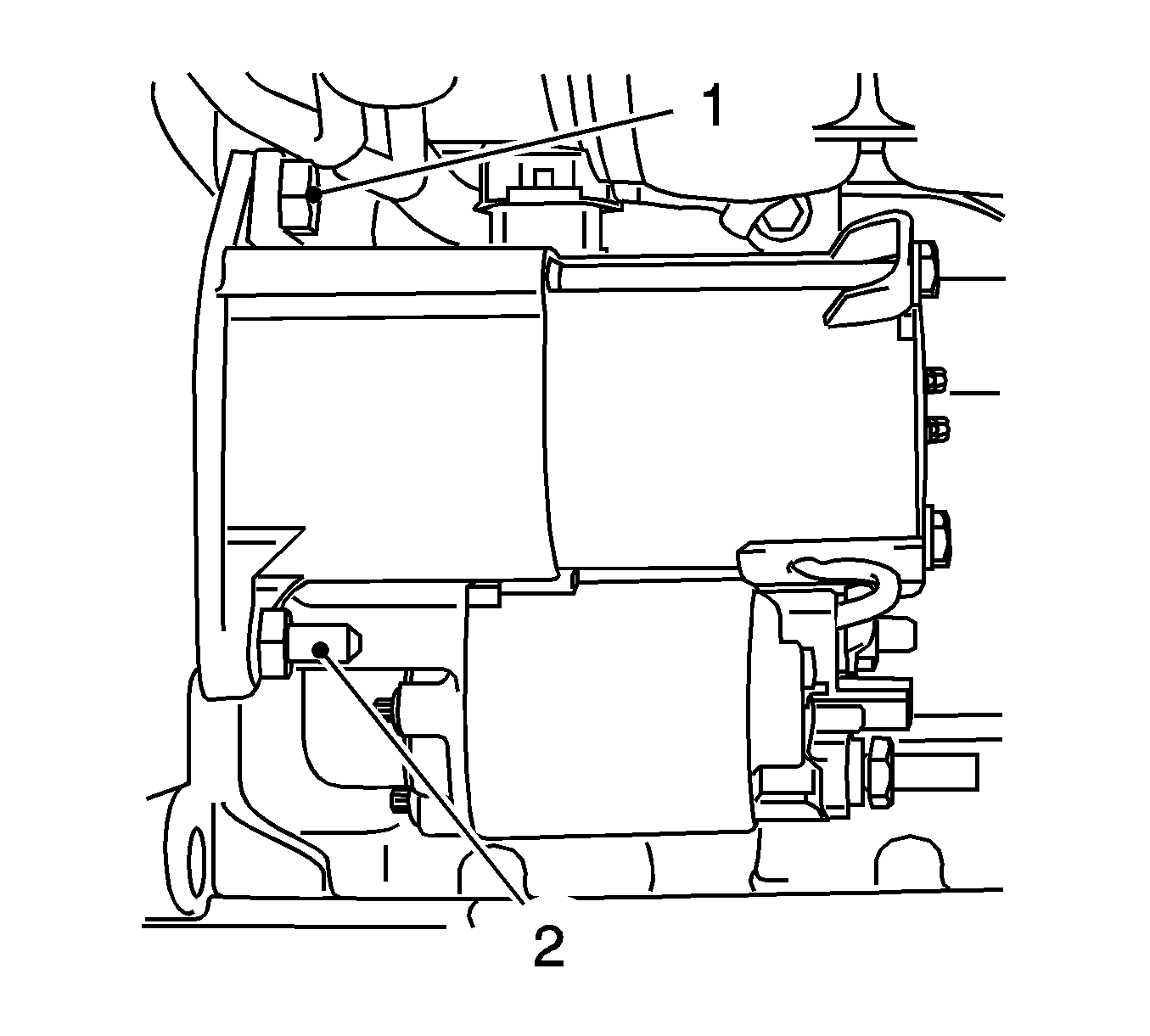
- Remove the starter.
| • | Unclip the wiring harness plug for the oxygen sensor of the catalytic converter control from the bracket. |
| • | Remove the 2 bolts (1, 2). |

- Attach
OTC 1726
(1).
Tighten the 3 bolts (2)
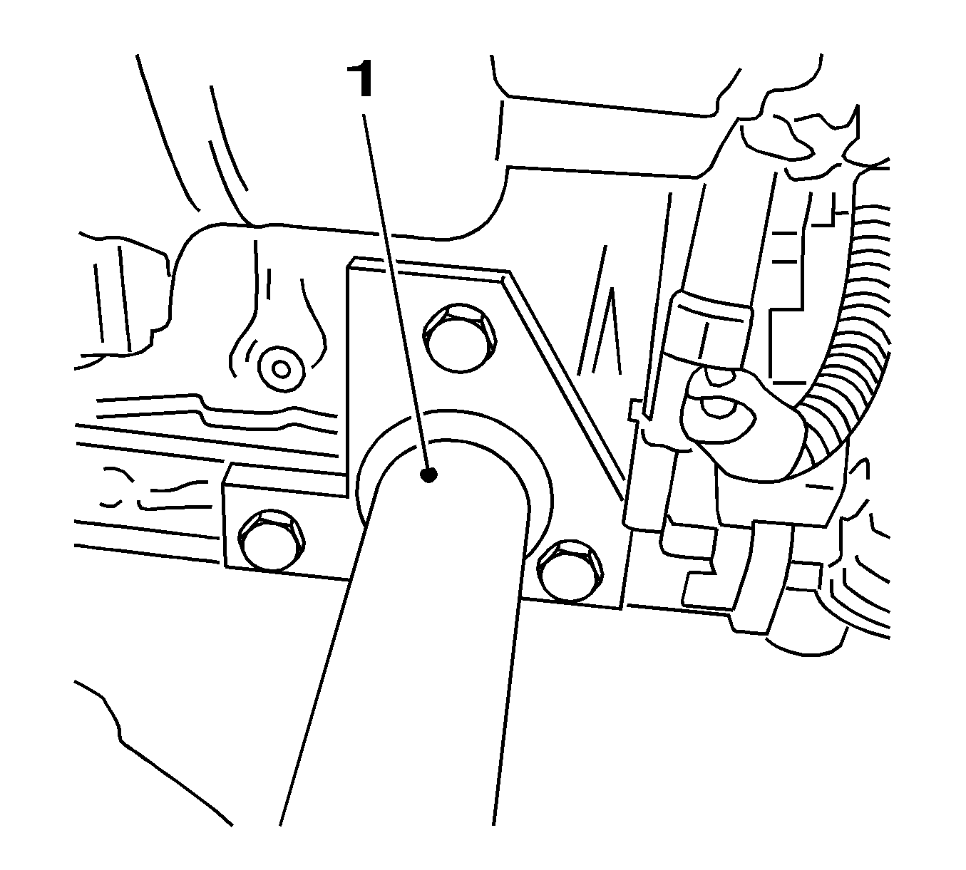
- Install
OTC 1726
(1).
Tighten the 3 bolts.
- Attach the engine up to the workshop crane.
Install the holding ropes to the engine transport shackles.
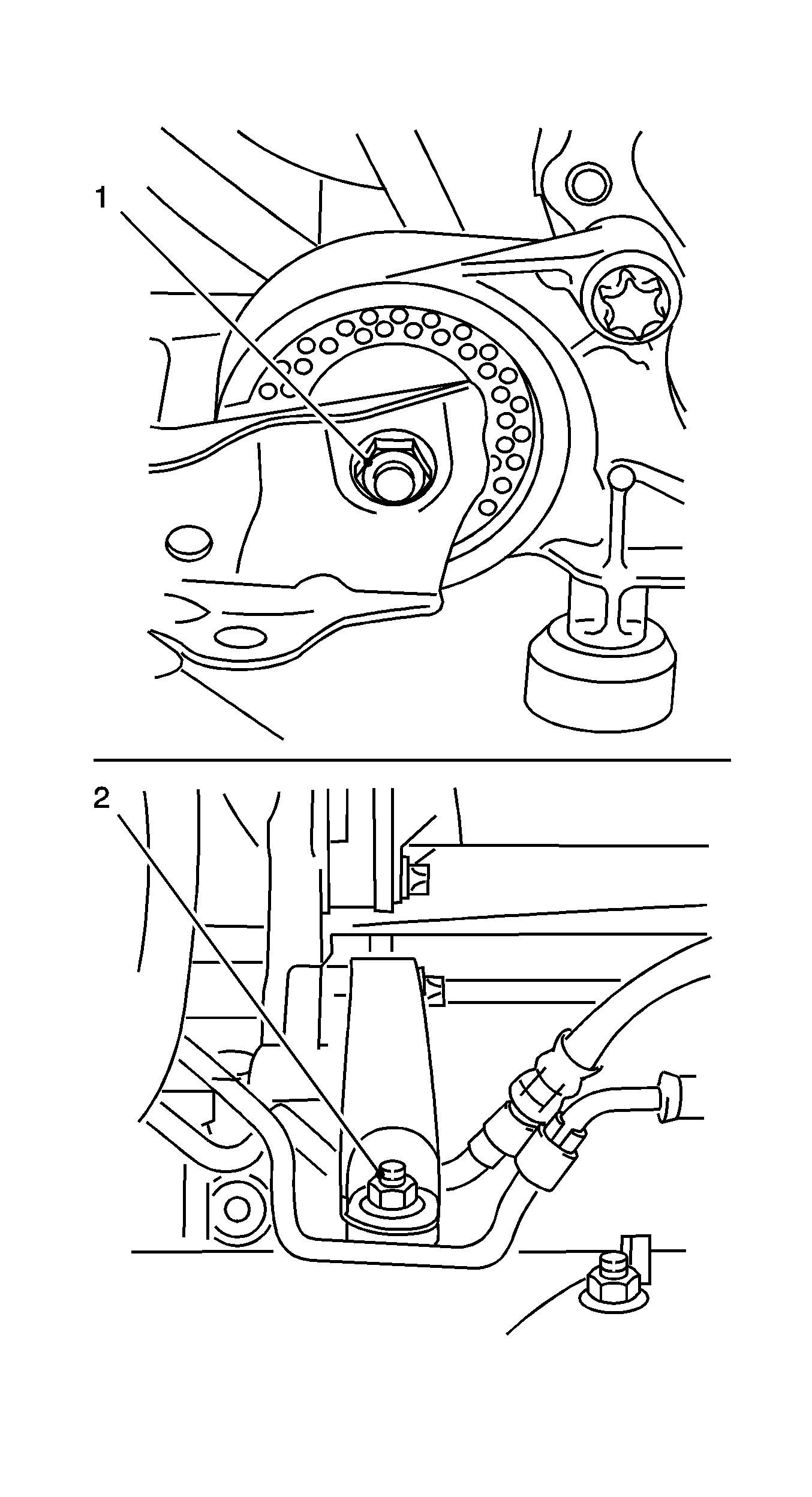
- Remove the front engine damping block.
Remove the screwed connection (1).
- Remove the rear engine damping block.
Remove the screwed connection (2).
- Lift the motor away from the front frame.
- Install the engine on the engine overhaul stand
OTC 1726
.
Remove the holding ropes from the engine transport shackles.
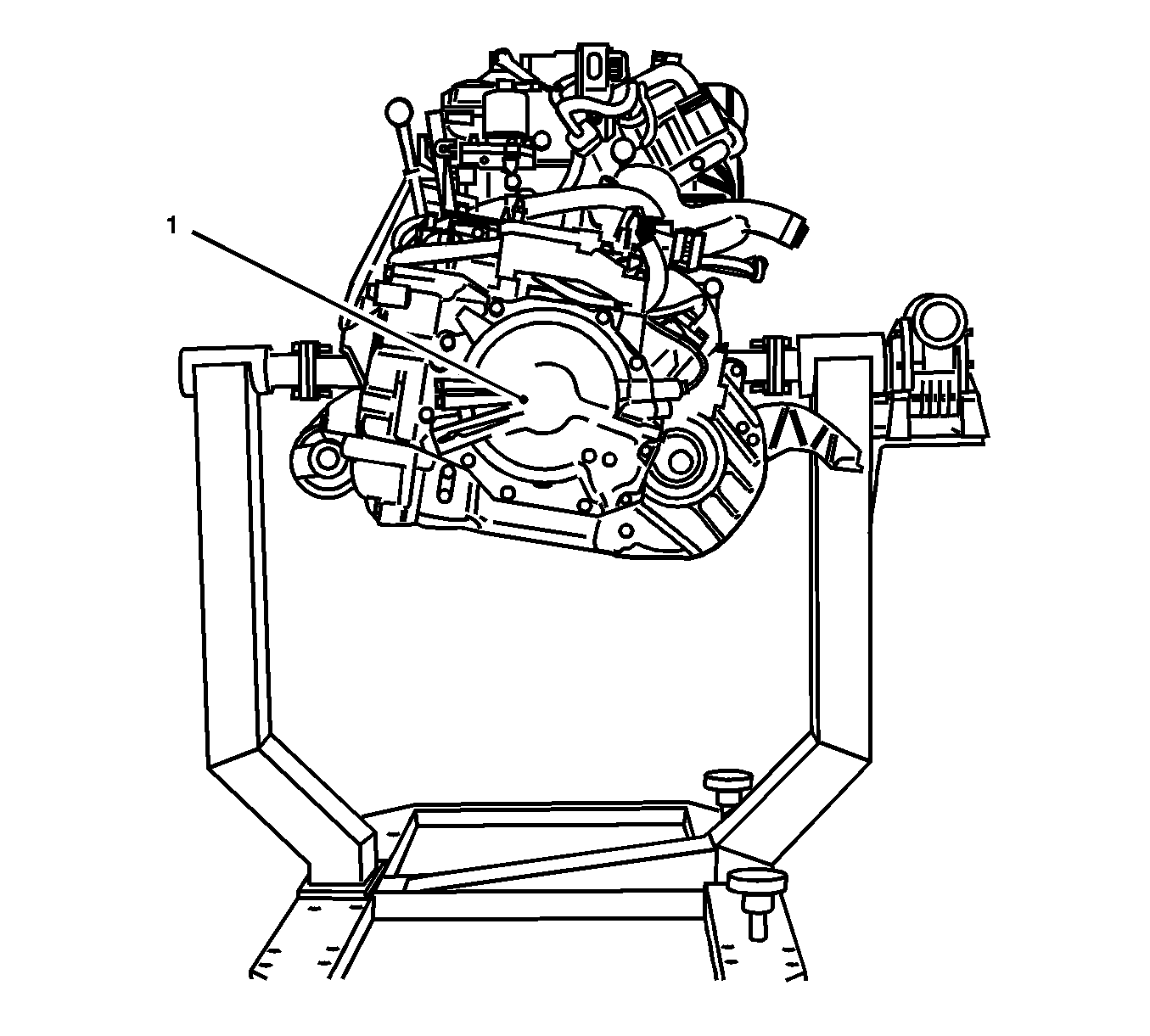
Important: One bolt remains as a retaining device.
- Remove the transmission (1) from the engine.
Remove 8 bolts.
- Remove the transmission.
| • | Install the holding ropes. |
| • | Attach the transmission up to the workshop crane. |
| | Important: Ensure that the attached parts and the wiring harnesses are undamaged.
|
Installation Procedure
- Install the transmission.
| • | Attach the transmission up to the workshop crane. |
| • | Install the transmission to the engine. |
| • | Disconnect the workshop crane. |
| • | Remove the holding ropes. |
Notice: Refer to Fastener Notice in the Preface section.
- Install the transmission to the engine.
| • | Install the transmission to the cylinder block. |
Tighten
Tighten the 4 bolts to 60 N·m (44 lb ft).
| • | Install the transmission to the oil pan. |
Tighten
Tighten the 3 bolts to 40 N·m (30 lb ft).
- Hitch the engine up to the workshop crane.
Install holding ropes to the engine transport shackles.
- Remove the engine from the engine overhaul stand
OTC 1726
.
Raise the engine carefully.
- Install the rear engine damping block, front frame.
Tighten
Tighten the screwed joint to 55 N·m (40 lb ft).
- Use new nuts.
- Install the front engine damping block to the front frame.
Tighten
Tighten the screwed joint to 55 N·m (40 lb ft).
- Use new nuts.
- Remove
OTC 1726
and
OTC 1726
from the cylinder block.
Remove the 6 bolts.
- Install the generator.
Tighten
Tighten the 2 bolts to 35 N·m (26 lb ft).
- Fit the starter.
Tighten
Tighten the 2 bolts to 25 N·m (18 lb ft).
- Clip in the wiring harness plug for the oxygen sensor of the catalytic converter control to bracket.
- Install the starter wiring harness.
Tighten
Tighten the 2 nuts to 12.5 N·m (110 lb in).
| • | Install the ground cable. |
Tighten
Tighten the nut to 5 N·m (44 lb in).
- Connect the alternator wiring harness.
Tighten
Tighten the 2 nuts to 7 N·m (67 lb in).
- Install the intake manifold bracket.
Tighten
Tighten the 2 bolts to 8 N·m (70 lb in).
| • | Connect the wiring harness plug into the bracket. |
| • | Connect the wiring harness plug for the catalytic converter control oxygen sensor. |
- Clean the sealing surface.
- Replace the 4 coolant pipe seal rings.
| • | Remove the 2 coolant pipes from the oil filter adapter. |
| • | Install the 2 coolant pipes in the oil filter adapter. |
- Install the oil filter adapter.
Tighten
Tighten the 4 bolts to 25 N·m (18 lb ft).
| • | O-rings with white silicone grease |
- Install the coolant pipe to the coolant module.
| • | Draw the coolant pipe out of the oil filter adapter. |
| • | Install the coolant pipe to the oil filter adapter. |
Tighten
Tighten the bolt to 25 N·m (18 lb ft).
- Install the coolant pipe to the coolant module.
Draw the coolant pipe out of the oil pump housing.
Tighten
Tighten the 2 bolts to 25 N·m(18 lb ft) .
- Remove the coolant pipe, oil filter housing to the thermostat housing.
| • | Push into the oil filter housing. |
| • | Connect to the thermostat housing. |
Tighten
Tighten the 2 bolts to 8 N·m (70 lb in).
- Install the compressor.
Tighten
Tighten the 3 bolts to 22 N·m (16 lb ft).
- Clean the sealing surface.
- Install the exhaust manifold with the catalytic converter.
Tighten
Tighten the 9 new nuts to 20 N·m (15 lb ft).
| • | Install the bracket to the cylinder block. |
Tighten
Tighten the 2 bolts to 20 N·m (15 lb ft).
- Install the heat shield.
Tighten
Tighten the 3 bolts to 8 N·m (70 lb in).
Important: Be careful of the wiring harness bracket.
- Install the wiring harness plug of the catalytic converter control oxygen sensor.
| • | Install the wiring harness plug. |
- Install the dipstick guide tube.
| • | Insert the guide tube into the oil pan. |
Tighten
Tighten the bolt to 8 N·m (70 lb in).
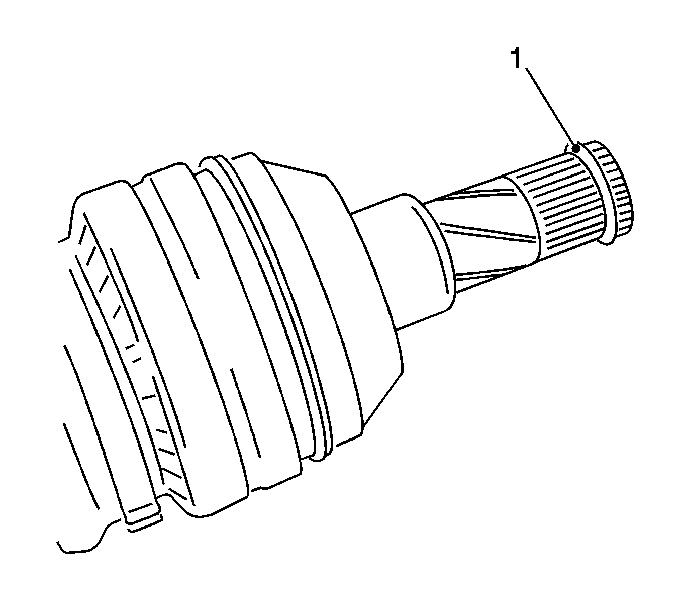
- Install the left-hand axle body.
| • | Attach the new circlip (1) to the axle body. |
| • | Lubricate the teeth and the bearing points with engine oil. |
| • | Push the axle body into the transmission until the circlip engages. |
- Install the right-hand axle body.
| • | Attach the new circlip to the front frame. |
| • | Lubricate the teeth and the bearing points with engine oil. |
| • | Push the axle body into the transmission until the circlip engages. |
- Place the cooling module in position.
- Connect the 3 wiring harness plugs.
| • | Temperature sensor, radiator |
| • | Manometric switch, condenser |
| • | Install the wiring harness. |
- Install the refrigerant line to the compressor.
Use a new gasket.
Tighten
Tighten the bolt to 20 N·m (15 lb ft).
- Install the lower radiator hose to the radiator.
- Install the upper radiator hose to the thermostat.
Fasten the clamp.
- Install the coolant return hose, throttle valve pre-heating to coolant surge tank.
- Inspect and correct the transmission fluid level. Refer to
Front Wheel Drive Shaft Seal Replacement
.


