For 1990-2009 cars only
Tools Required
J 45059 Angle Meter
Removal Procedure
- Raise and support the vehicle. Refer to Lifting and Jacking the Vehicle .
- Remove the wheel. Refer to Tire and Wheel Removal and Installation .
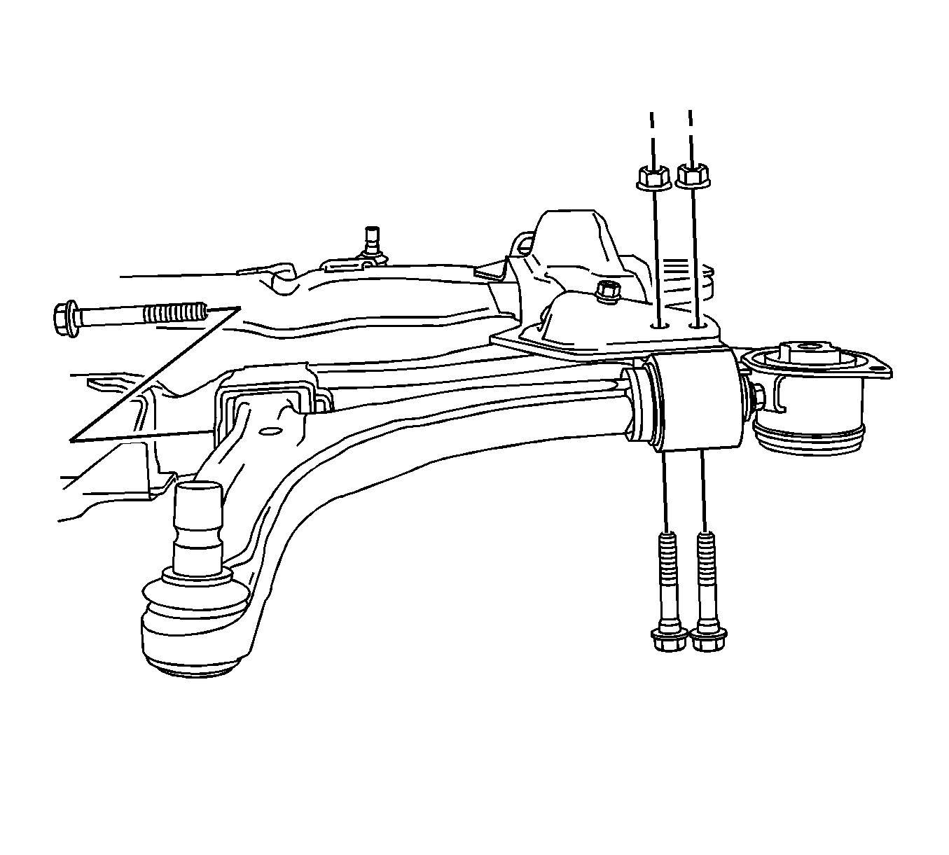
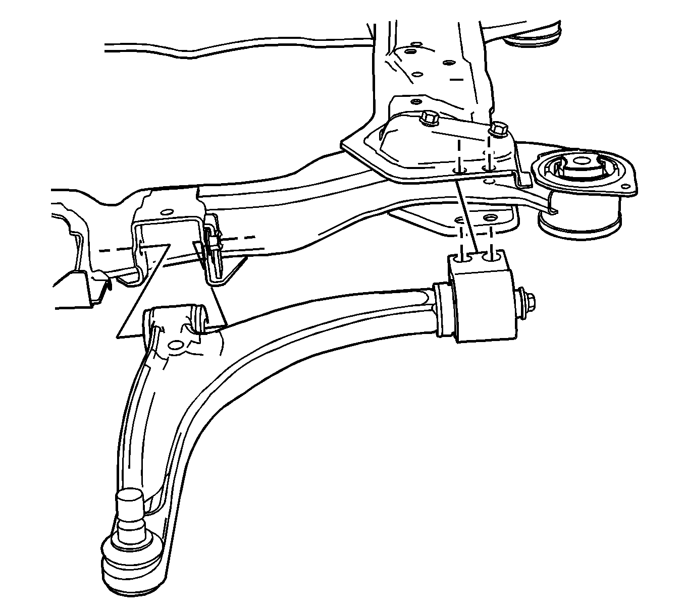
- Remove the front lower control arm bushing to frame bolt and nut.
- Remove the rear lower control arm bushing to frame bolts and nuts.
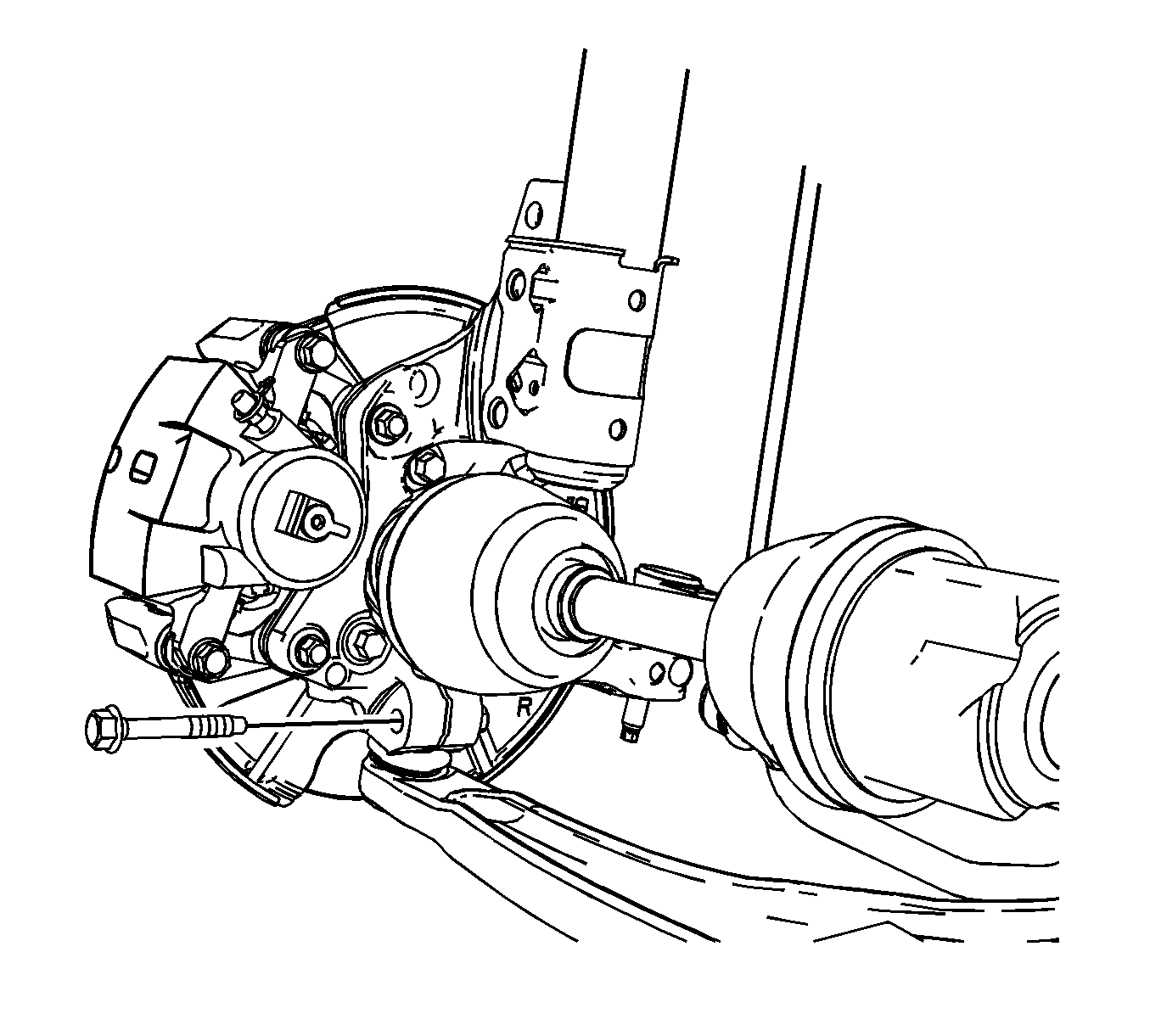
- Prior to removal, note the orientation of the lower control arm ball stud to steering knuckle pinch bolt and remove the pinch bolt and discard.
- Separate the ball stud from the steering knuckle.
- Remove the control arm from the vehicle.
- Remove the rear lower control arm bushing. Refer to Front Lower Control Arm Bushing Replacement .


Installation Procedure
- Install the rear lower control arm bushing. Refer to Front Lower Control Arm Bushing Replacement .
- Position the lower control arm to the frame assembly and steering knuckle.
- Note the previous orientation and install the a new ball stud to the steering knuckle pinch bolt. Hand tighten only.
- Install the front bushing to frame bolt and nut. Hand tighten only.
- Install the rear bushing to frame bolts and nuts.
- Tighten the ball stud to steering knuckle pinch nut to 50 N·m (37 lb ft).
- Tighten the nuts and the bolts with the front suspension loaded by using the proper jackstand.
- Tighten the front bushing to frame bolt to 50 N·m (37 lb ft). Using the J 45059 , rotate an additional 90 degrees.
- Tighten the rear bushing to frame nuts to 50 N·m (37 lb ft). Using the J 45059 , rotate an additional 90 degrees.
- Install the tire and wheel. Refer to Tire and Wheel Removal and Installation .
- Lower the vehicle.


Notice: Refer to Fastener Notice in the Preface section.
Tighten
Reverse the nut 3/4 of a turn .
Tighten to 50 N·m (37 lb ft). Using the J 45059 , rotate an additional 30 degrees.
