Removal Procedure
Caution: Refer to Approved Equipment for Collision Repair Caution in the Preface section.
- Disable the SIR system. Refer to SIR Disabling and Enabling .
- Disconnect the negative battery cable. Refer to Battery Negative Cable Disconnection and Connection .
- Remove all related panels and components.
- Repair as much of the damage as possible to factory specifications
- Remove the sealers and anti-corrosion materials from the repair area, as necessary. Refer to Anti-Corrosion Treatment and Repair .
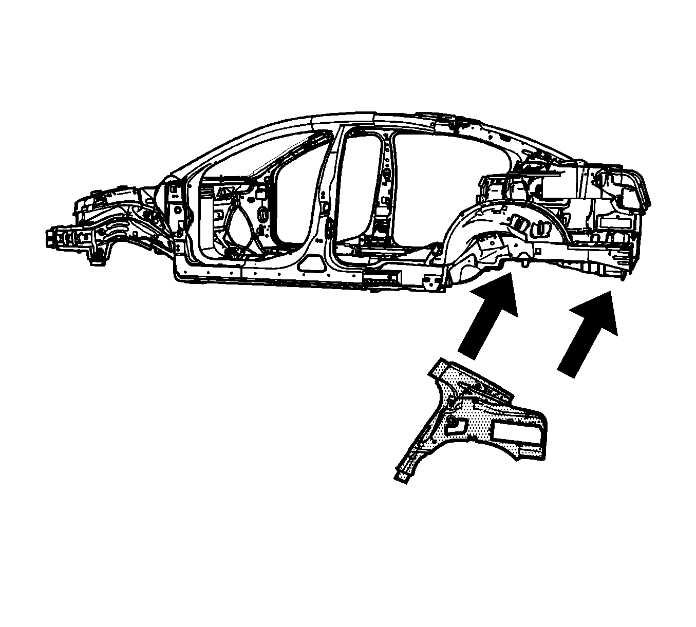
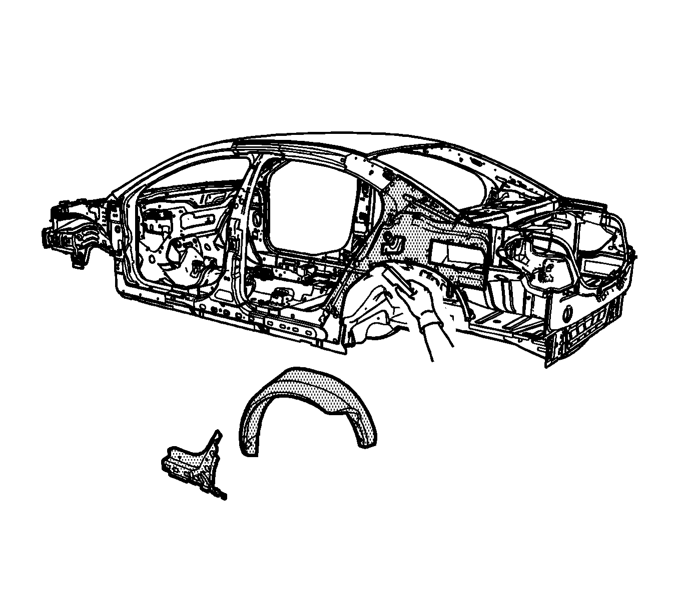
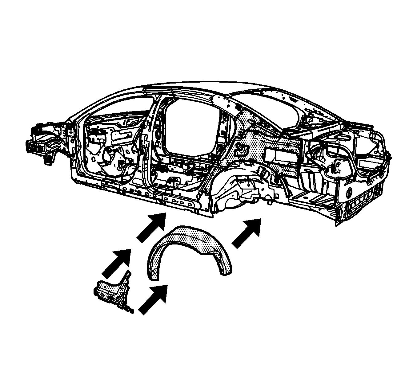
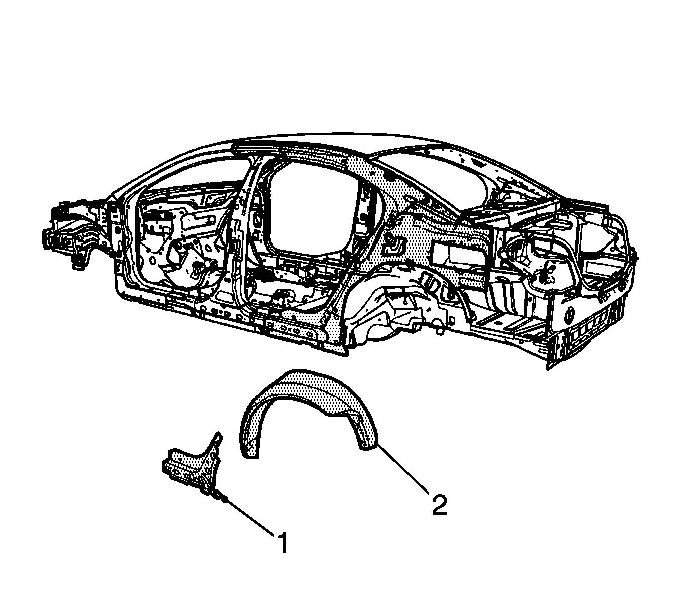
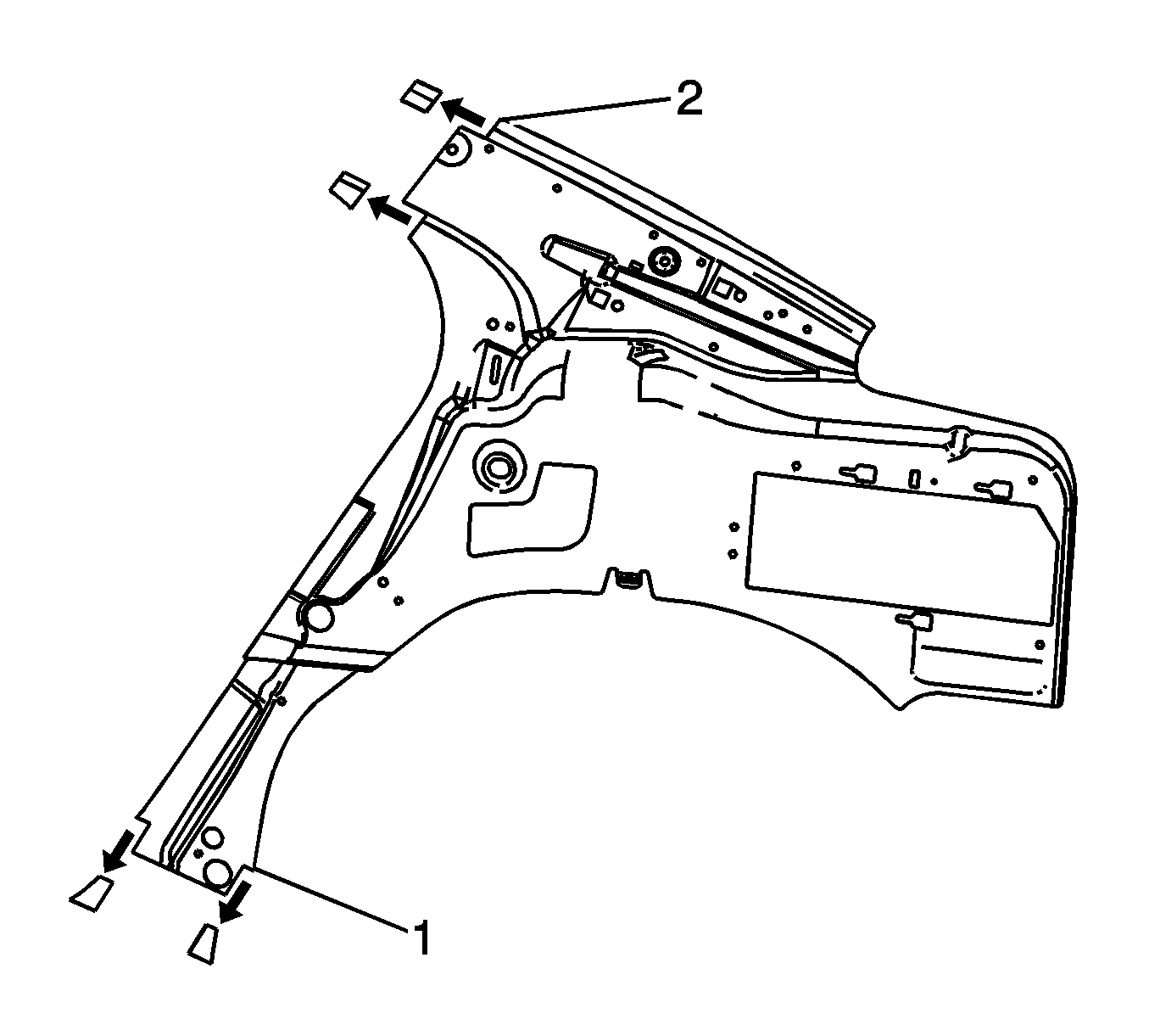
- Remove the body inner reinforcement and the outer wheelhouse (2).
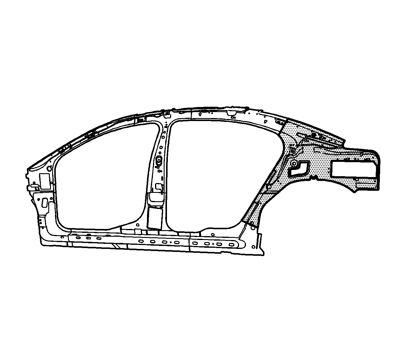
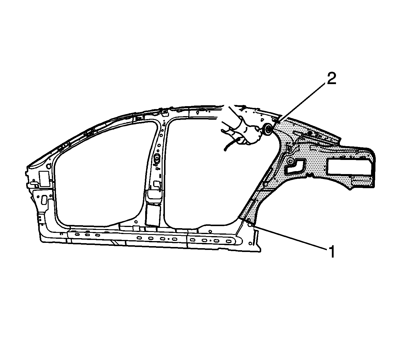
- In the dog leg panel area, measure 100 mm (4 in) upward from the locating hole (1). Scribe a line. This is the cut line.
- On the upper inner quarter panel area, measure 100 mm (4 in) down from the locating hole (2). This is the cut line.
- Locate, mark, and drill out all the necessary factory welds.
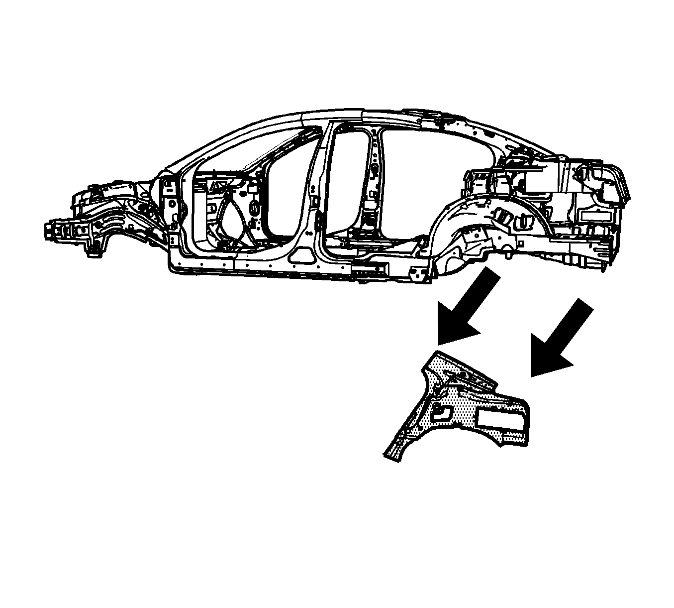
- Remove the damaged wheelhouse section.
Caution: Sectioning should be performed only in the recommended areas. Failure to do so may compromise the structural integrity of the vehicle and cause personal injury if the vehicle is in a collision.
Important: The inner side frame is a stamped one-piece service part. The frame may be replaced either as a full part or sectioned as needed, as determined by the damaged area.

Important: Do not damage any inner panels or reinforcements. The rear rocker area contains a nylon reinforcement that may be replaced if damaged.
Important: Note the number and location of the factory welds for installation of the inner quarter panel.
Installation Procedure
- Cut the service part 50 mm (2 in) upward from the dog leg locating hol (1) and 50 mm (2 in) down from the upper inner locating hole (2) as noted.
- At the cut edge of the service panel in the dog leg area, measure upward 50 mm (2 in) (1). Notch out the upper innerr panel flange to allow the underlap to the existing panel.
- Drill 8 mm (5/16 in) plug weld holes along the sectioning cut on the original reinforcement. Locate these holes 25 mm (1 in) from the edge and spaced 40 mm (1½ in) apart.
- Drill 8 mm (5/16 in) plug weld holes in the service reinforcement as necessary in the locations noted from the original panel.
- Prepare all mating surfaces as necessary.
- Apply GM--approved Weld-Thru Coating or equivalent to all mating surfaces. Refer to Anti-Corrosion Treatment and Repair .
- Align the service part on the vehicle using 3-dimensional measuring equipment.
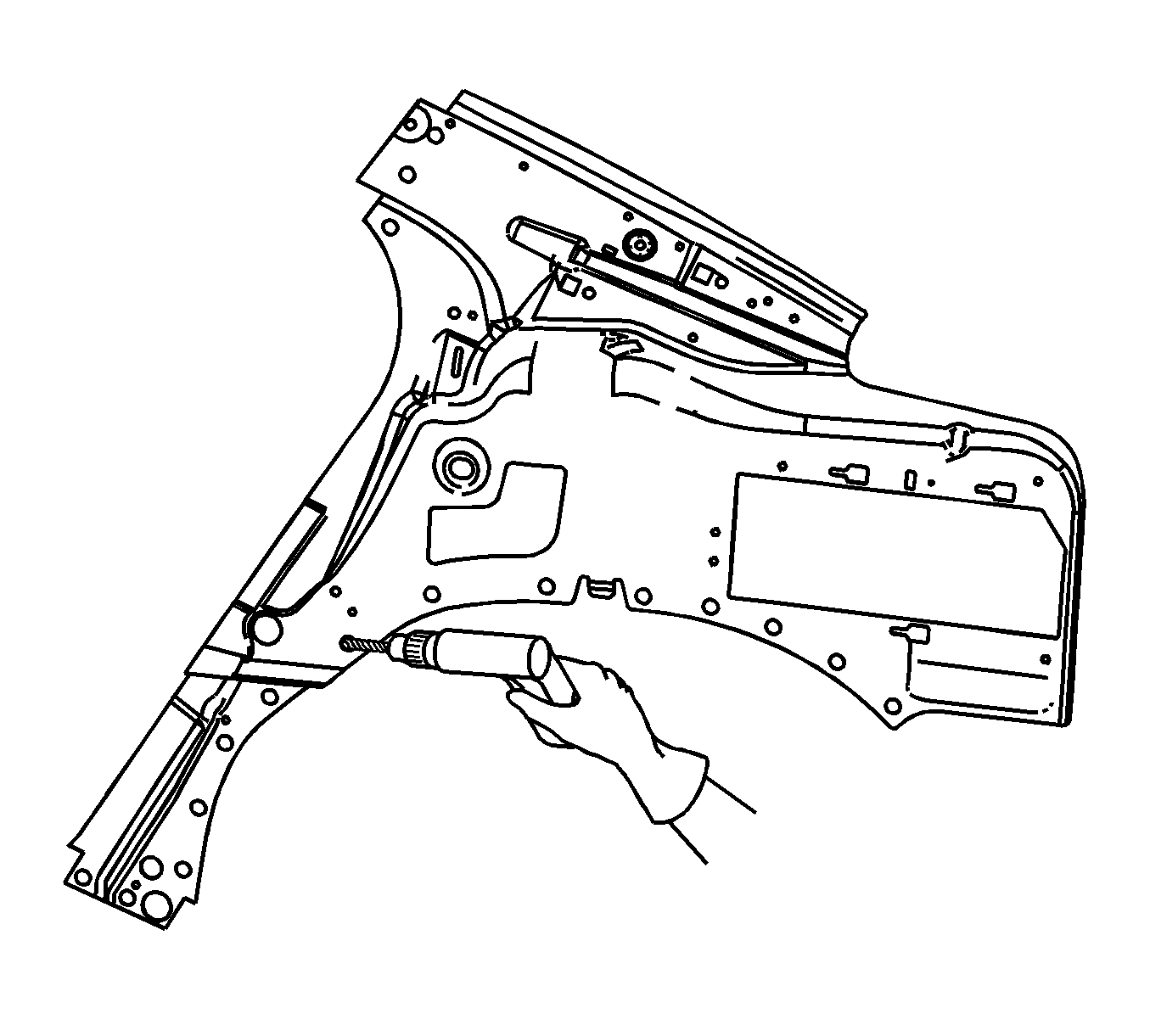
- Plug weld accordingly.
- To create a solid weld with minimum heat distortion, make 25 mm (1 in) stitch welds along the seam with 25 mm (1 in) gaps between them. Go back and complete the stitch weld.
- Install the body inner reinforcement and the outer wheelhouse.
- Clean and prepare all of the welded surfaces.
- Apply the sealers and anti-corrosion materials to the repair area, as necessary. Refer to Anti-Corrosion Treatment and Repair .
- Paint the repaired area. Refer to Basecoat/Clearcoat Paint Systems .
- Install all of the related panels and components.
- Connect the negative battery cable. Refer to Battery Negative Cable Disconnection and Connection .
- Enable the SIR system. Refer to SIR Disabling and Enabling .
Important: If the location of the original plug weld holes can not be determined, space the plug weld holes every 40 mm (1 1/2 in) apart.