| Table 1: | A/C Fresh/Recirculation Switch |
| Table 2: | Defogger Mode Switch |
| Table 3: | Fresh/Recirculation Air Inlet Actuator |
| Table 4: | Blower Motor |
| Table 5: | Blower Motor Resistor |
| Table 6: | Blower Switch |
| Table 7: | Evaporator Temperature Sensor |
| Table 8: | Fan Motor |
| Table 9: | Fan Resistor |
| Table 10: | Refrigerant Pressure Switch |
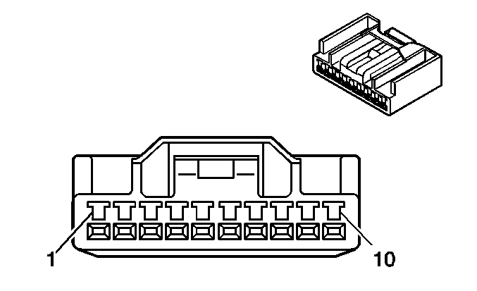
| ||||||
|---|---|---|---|---|---|---|
Connector Part Information |
| |||||
Pin | Wire Color | Function | ||||
1 | WH/BK | Ground | ||||
2 | GN/WH | Fresh Position Actuator Control | ||||
3 | -- | Not Used | ||||
4 | RD/WH | AC Switch Feed Circuit | ||||
5 | BU/WH | Recirculation Position Actuator Control | ||||
6 | GN | Illumination Lamps Supply Voltage | ||||
7 | WH/BK | Illumination Lamps Ground | ||||
8 | GN/WH | A/C Indicator Control | ||||
9 | YE | AC Request Signal Circuit | ||||
10 | BK | AC Request Feed Circuit | ||||
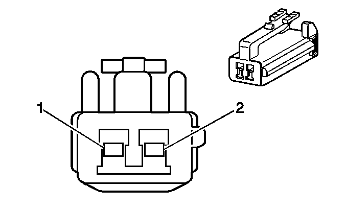
| ||||||
|---|---|---|---|---|---|---|
Connector Part Information |
| |||||
Pin | Wire Color | Function | ||||
1 | YE | AC Request Signal Circuit | ||||
2 | BK | AC Request Feed Circuit | ||||
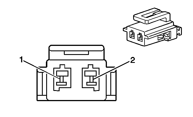
| ||||||
|---|---|---|---|---|---|---|
Connector Part Information |
| |||||
Pin | Wire Color | Function | ||||
1 | GN/WH | Fresh Position Control | ||||
2 | BU/WH | Recirculation Position Control | ||||
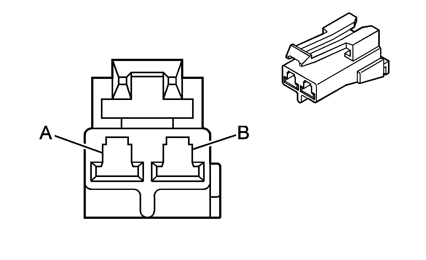
| ||||||
|---|---|---|---|---|---|---|
Connector Part Information |
| |||||
Pin | Wire Color | Function | ||||
A | BK | Blower Motor Feed Circuit | ||||
B | BK/WH | Blower Motor Resistor Control Circuit | ||||
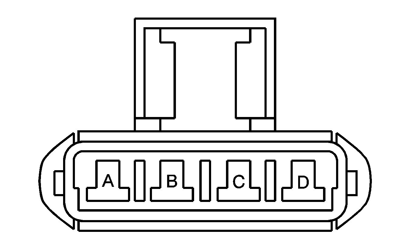
| ||||||
|---|---|---|---|---|---|---|
Connector Part Information |
| |||||
Pin | Wire Color | Function | ||||
A | RD | Ground | ||||
B | LT BU | Medium 1 | ||||
C | BK/WH | Medium 2 | ||||
D | WH/BK | High | ||||
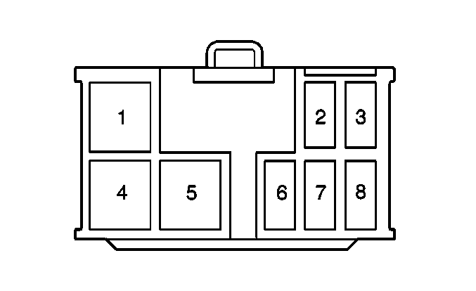
| ||||||
|---|---|---|---|---|---|---|
Connector Part Information |
| |||||
Pin | Wire Color | Function | ||||
1 | BU/WH | Blower Control Medium 2 | ||||
2 | RD | Blower Control Medium 1 | ||||
3 | WH/BK | Illumination Ground | ||||
4 | BK/WH | Blower Control High | ||||
5 | WH/BK | Ground | ||||
6 | BU/WH | Heater Relay Control Circuit | ||||
7 | -- | Not Used | ||||
8 | GN | Illumination Supply Voltage | ||||
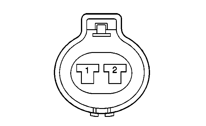
| ||||||
|---|---|---|---|---|---|---|
Connector Part Information |
| |||||
Pin | Wire Color | Function | ||||
1 | BK/BU | Sensor High | ||||
2 | BN | Sensor Low | ||||

| ||||||
|---|---|---|---|---|---|---|
Connector Part Information |
| |||||
Pin | Wire Color | Function | ||||
1 | WH/RD | Fan Motor Control Circuit | ||||
2 | BK/RD | Fan Motor Feed Circuit | ||||

| ||||||
|---|---|---|---|---|---|---|
Connector Part Information |
| |||||
Pin | Wire Color | Function | ||||
1 | WH/BK | Ground | ||||
2 | BU/WH | Low Speed Fan Control Circuit | ||||
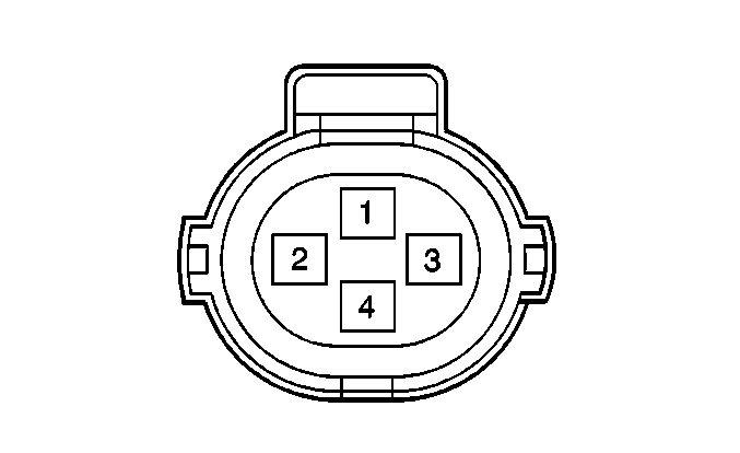
| ||||||
|---|---|---|---|---|---|---|
Connector Part Information |
| |||||
Pin | Wire Color | Function | ||||
1 | YE | Pressure Signal to PCM | ||||
2 | WH/BK | Ground | ||||
3 | LT GN/BK | High Speed Fan Control | ||||
4 | WH/BK | Ground | ||||
