For 1990-2009 cars only
Removal Procedure
- Remove the starter motor. Refer to Starter Motor Replacement .
- Disconnect the knock sensor (KS) electrical connector.
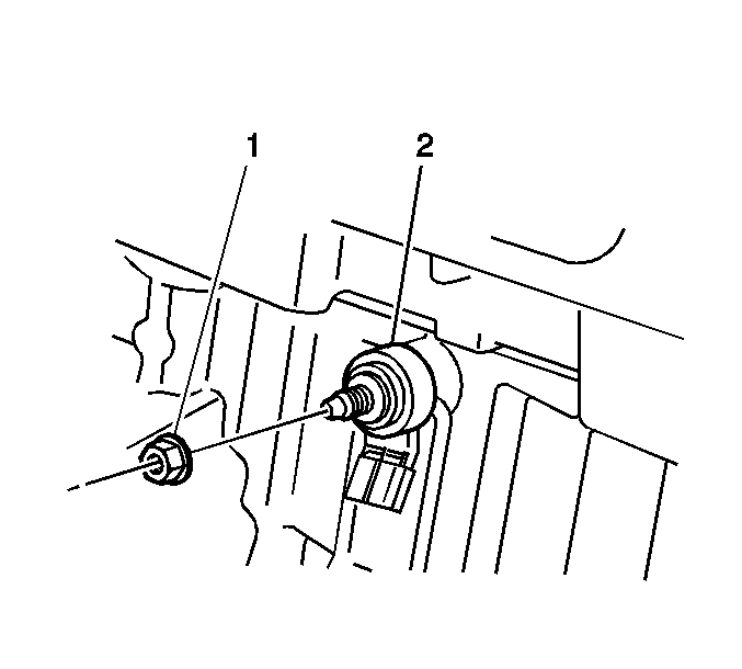
- Remove the nut (1) securing the KS (2) to the engine block.
- Remove the KS (2) from the engine block.

Installation Procedure
- Install the KS (2) onto the threaded stud in the engine block.
- Install the KS nut (1) to the threaded stud.
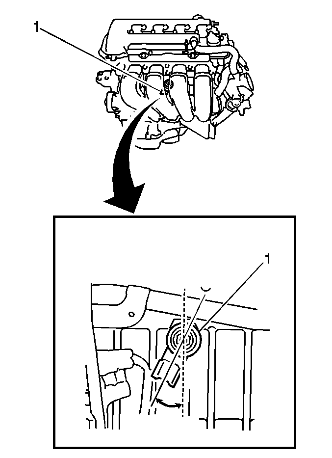
- Align the KS (1) on the engine block as illustrated. The KS electrical connector cavity must point down, in a 15-30 degree arc from perpendicular to the earth.
- Tighten the KS nut while maintaining the correct sensor alignment.
- Connect the KS electrical connector.
- Install the starter motor. Refer to Starter Motor Replacement .

Important: In order to prevent water accumulation in the KS electrical connector cavity, install the KS with the connector cavity pointing down.

Notice: Replacement components must be the correct part number for the application. Components requiring the use of the thread locking compound, lubricants, corrosion inhibitors, or sealants are identified in the service procedure. Some replacement components may come with these coatings already applied. Do not use these coatings on components unless specified. These coatings can affect the final torque, which may affect the operation of the component. Use the correct torque specification when installing components in order to avoid damage.
Tighten
Tighten the nut to 20 N·m (16 lb ft).
