Symbol | Description |
|---|---|
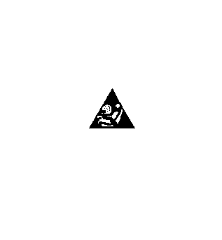
| Supplemental Inflatable Restraint (SIR) or Supplemental Restraint System (SRS) Icon This icon is used to alert the technician that the system contains SIR/SRS components that require certain precautions before servicing. Refer to SIR Caution in Cautions and Notices. |
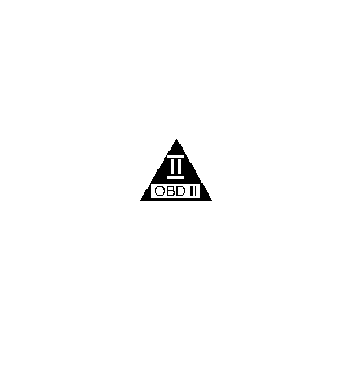
| On-Board Diagnostic (OBD II) Icon This icon is used to alert the technician that the circuit is essential for proper OBD II emission controls circuit operation. Any circuit which, if it fails, causes the malfunction indicator lamp (MIL) to turn on, is identified as an OBD II circuit. |

| Important Icon This icon is used to alert the technician that there is additional information that will aid in servicing a system. |
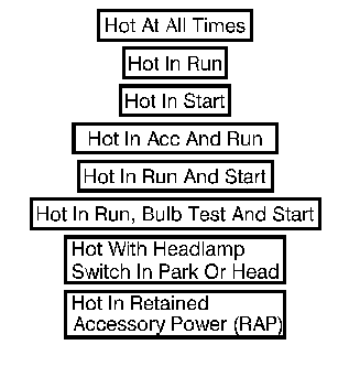
| Voltage Indicator Boxes These boxes are used on schematics to indicate when voltage is present at a fuse. |

| Partial Component When a component is represented in a dashed box, the component or its wiring is not shown in its entirety. |

| Entire Component When a component is represented in a solid box the component or its wiring is shown in its entirety. |
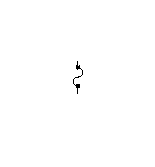
| Fuse |
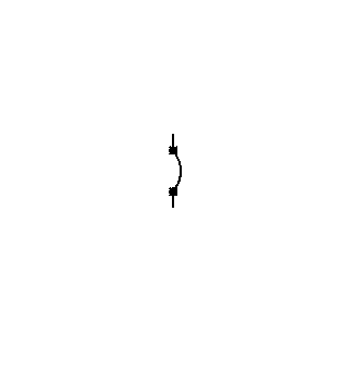
| Circuit Breaker |
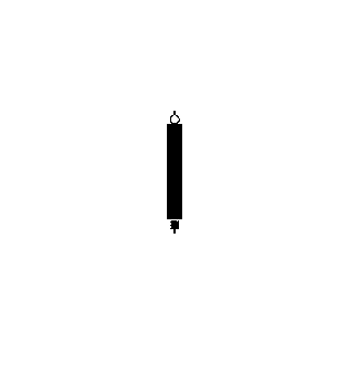
| Fusible Link |
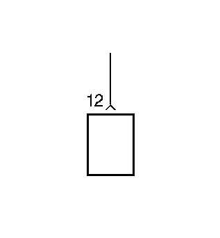
| Connector Attached to Component |
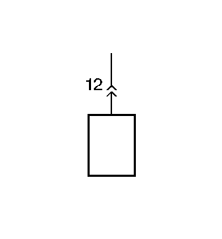
| Pigtail Connector |
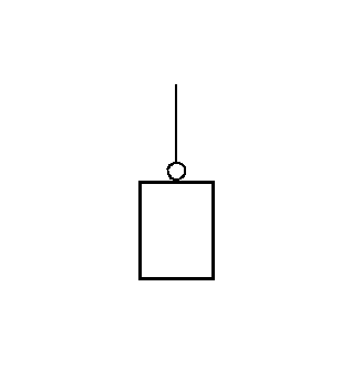
| Bolt On or Screw On Eyelet Terminal |
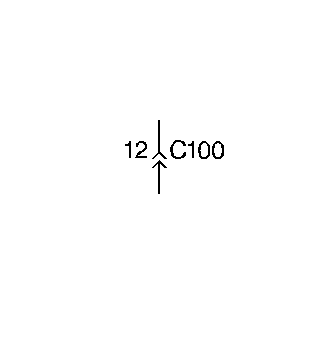
| Inline Harness Connector |
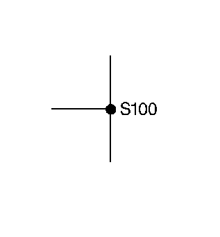
| Splice |
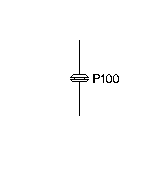
| Pass Through the Grommet |
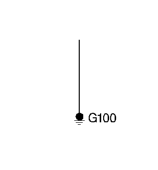
| Chassis Ground |
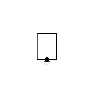
| Case Ground |
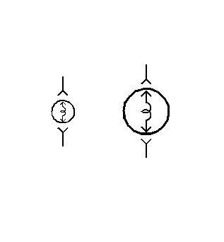
| Single Filament Light Bulbs |
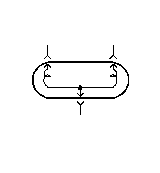
| Double Filament Light Bulb |
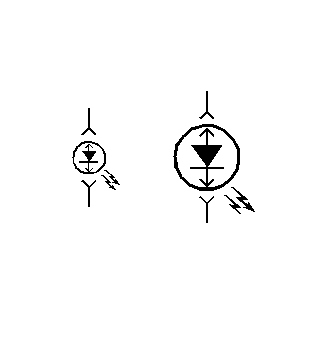
| Light Emitting Diodes |

| Capacitor |

| Battery |

| Variable Battery |
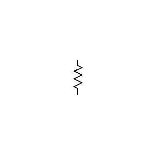
| Resistor |
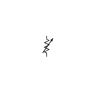
| Variable Resistor |
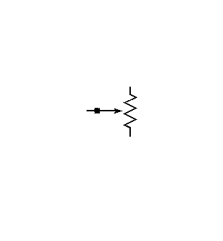
| Position Sensor |
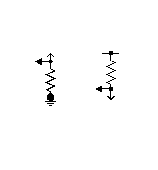
| I/O Resistors |
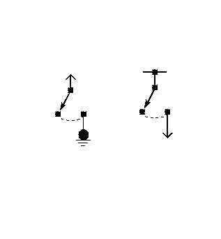
| I/O Switches |
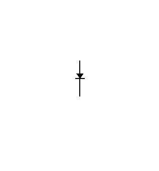
| Diode |
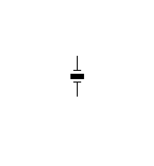
| Crystal |

| Heating Elements |
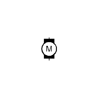
| Motor |

| Solenoid |
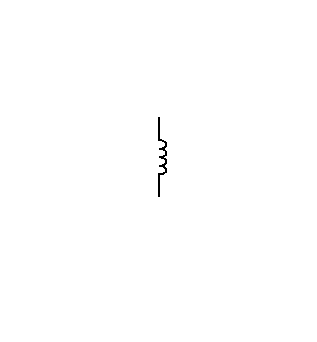
| Coil |
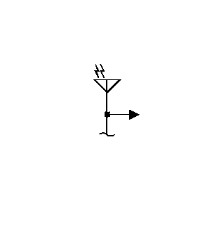
| Antenna |
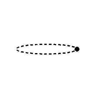
| Shield |
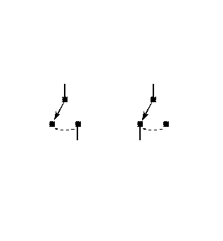
| Switches |
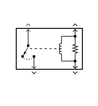
| Single Pole Single Throw Relay |
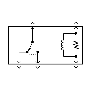
| Single Pole Double Throw Relay |
