
| |||||||||||||
|---|---|---|---|---|---|---|---|---|---|---|---|---|---|
Connector Part Information |
| Connector Part Information |
| ||||||||||
Pin | Wire Color | Function | Pin | Wire Color | Function | ||||||||
1-2 | -- | Not Used | 1-2 | -- | Not Used | ||||||||
3 | BLK/WHT | EFI Supply Voltage | 3 | BLK/WHT | EFI Supply Voltage | ||||||||
4 | BLK/WHT | AC Clutch Supply Voltage | 4 | BLK/WHT | AC Clutch Supply Voltage | ||||||||
5 | WHT | Alternator Supply Voltage | 5 | WHT | Alternator Supply Voltage | ||||||||
6-7 | -- | Not Used | 6-7 | -- | Not Used | ||||||||
8 | YEL | Refridgerant Pressure Switch PCM Signal | 8 | YEL | Refridgerant Pressure Switch PCM Signal | ||||||||
9 | BLK | EFI Relay PCM Signal Voltage | 9 | BLK | EFI Relay PCM Signal Voltage | ||||||||
10 | BLK/WHT | Ignition Coils Supply Voltage | 10 | BLK/WHT | Ignition Coils Ignition Supply Voltage | ||||||||
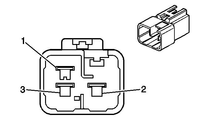
|
| ||||||||||||
|---|---|---|---|---|---|---|---|---|---|---|---|---|---|
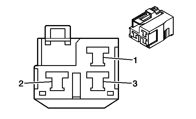
Connector Part Information |
| Connector Part Information |
| ||||||||||
Pin | Wire Color | Function | Pin | Wire Color | Function | ||||||||
1 | RED/BLK | Daytime Running Lamps Control Module -- Low Beam Control | 1 | RED/BLK | Daytime Running Lamps Control Module -- Low Beam Control | ||||||||
2 | BLK/RED | Starter Relay Supply Voltage | 2 | BLK/RED | Starter Relay Supply Voltage | ||||||||
3 | WHT/BLK | Daytime Running Lamps Control Module | 3 | WHT/BLK | Daytime Running Lamps Control Module | ||||||||

| |||||||||||||
|---|---|---|---|---|---|---|---|---|---|---|---|---|---|
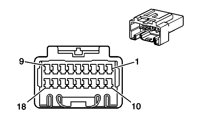
Connector Part Information |
| Connector Part Information |
| ||||||||||
Pin | Wire Color | Function | Pin | Wire Color | Function | ||||||||
1 | RED/WHT | Battery Positive Voltage | 1 | RED/WHT | Battery Positive Voltage | ||||||||
2 | BLU/RED | Rear Washer Pump Control | 2 | BLU/RED | Rear Washer Pump Control | ||||||||
3 | RED | Ignition Positive Voltage | 3 | RED | Ignition Positive Voltage | ||||||||
4 | RED/WHT | Headlamp Relay Control | 4 | RED/YEL | Headlamp Relay Control | ||||||||
5 | BLU/RED | Radio Amplifier Supply Voltage | 5 | BLU/RED | Radio Amplifier Supply Voltage | ||||||||
6 | BLU/WHT | Windshield Wiper Park Signal | 6 | BLU/WHT | Windshield Wiper Park Signal | ||||||||
7 | BLU/WHT | Windshield Wiper Low Speed Signal | 7 | BLU/WHT | Windshield Wiper Low Speed Signal | ||||||||
8 | BLU/RED | Windshield Wiper High Speed Signal | 8 | BLU/RED | Windshield Wiper High Speed Signal | ||||||||
9 | BLU/YEL | Windshield Washer Pump Supply Voltage | 9 | BLU/YEL | Windshield Washer Pump Supply Voltage | ||||||||
10 | WHT/RED | Headlamp Dimmer Relay Control | 10 | WHT/RED | Headlamp Dimmer Relay Control | ||||||||
|
| ||||||||||||
|---|---|---|---|---|---|---|---|---|---|---|---|---|---|
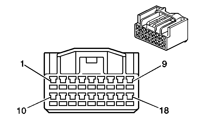
Connector Part Information |
| Connector Part Information |
| ||||||||||
Pin | Wire Color | Function | Pin | Wire Color | Function | ||||||||
1 | YEL | Deceleration SensorSignal | 1 | YEL | Deceleration Sensor Signal | ||||||||
2 | YEL/RED | Deceleration Sensor Signal | 2 | YEL/RED | Deceleration Sensor Signal | ||||||||
3 | WHT/BLK | Cruise Control Servo Ground | 3 | WHT/BLK | Cruise Control Servo Ground | ||||||||
4 | RED/GRN | Cruise Control Accel Signal | 4 | RED/GRN | Cruise Control Accel Signal | ||||||||
5 | RED/WHT | Cruise Control Release Switch Supply Voltage | 5 | RED/WHT | Cruise Control Release Switch Supply Voltage | ||||||||
6 | LT GRN/BLK | Fan 1 Relay PCM Control | 6 | LT GRN/BLK | Fan 1 Relay PCM Control | ||||||||
7 | LT GRN | Fan 2 Relay PCM Control | 7 | LT GRN | Fan 2 Relay PCM Control | ||||||||
8 | GRN/WHT | Flasher Relay Supply Voltage | 8 | GRN/WHT | Flasher Relay Supply Voltage | ||||||||
9 | RED/YEL | Fog Lamp Switch Relay Control | 9 | RED/YEL | Fog Lamp Switch Relay Control | ||||||||
10 | BLK | Ignition Positive Voltage | 10 | BLK | Ignition Positive Voltage | ||||||||
11 | YEL/BLK | Accelerometer Signal | 11 | YEL/BLK | Accelerometer Signal | ||||||||
12 | RED/BLU | Cruise Control Coast Signal | 12 | RED/BLU | Cruise Control Coast Signal | ||||||||
13 | GRN/ORN | Magnetic Clutch Control--Cruise Control | 13 | GRN/ORN | Magnetic Clutch Control--Cruise Control | ||||||||
14 | BLU | Ignition Positive Voltage -- Cruise Control Release Switch | 14 | BLU | Ignition Positive Voltage -- Cruise Control Release Switch | ||||||||
15 | RED/WHT | Brake Indicator Control | 15 | RED/WHT | Brake Indicator Control | ||||||||
16 | RED | Brake Indicator Control | 16 | RED | Brake Indicator Control | ||||||||
17 | RED/WHT | Brake Fluid Level Switch Signal | 17 | RED/WHT | Brake Fluid Level Switch Signal | ||||||||
18 | GRN/YEL | Horn Relay Control | 18 | GRN/YEL | Horn Relay Control | ||||||||
|
| ||||||||||||
|---|---|---|---|---|---|---|---|---|---|---|---|---|---|
Connector Part Information |
| Connector Part Information |
| ||||||||||
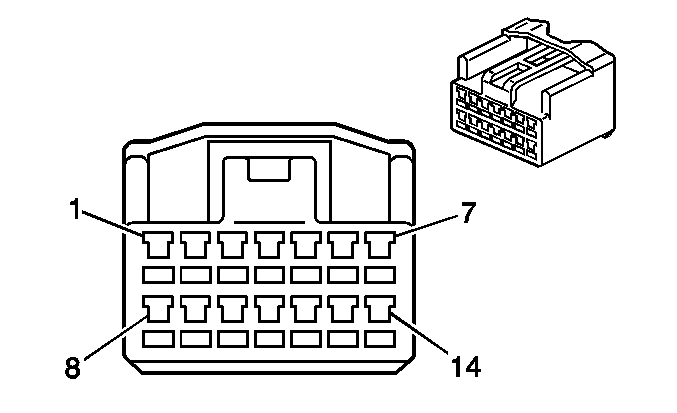
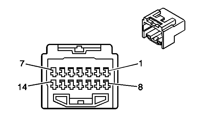
Pin | Wire Color | Function | Pin | Wire Color | Function | ||||||||
1 | -- | Not Used | 1 | -- | Not Used | ||||||||
2 | RED/WHT | High Beam Indicator Control | 2 | RED/WHT | High Beam Indicator Control | ||||||||
3 | BLK | Ambient Air Temperature Sensor Signal | 3 | BLK | Ambient Air Temperature Sensor Signal | ||||||||
4 | BLU/RED | Serial Data | 4 | BLU/RED | Serial Data | ||||||||
5 | WHT/RED | ABS Indicator Control | 5 | WHT/RED | ABS Indicator Control | ||||||||
6 | RED | Ignition Positive Voltage -- High Beam Indicator | 6 | RED | Ignition Positive Voltage -- High Beam Indicator | ||||||||
7 | YEL/BLK | A/C Compressor Clutch Relay Control | 7 | YEL/BLK | A/C Compressor Clutch Relay Control | ||||||||
8-9 | -- | Not Used | 8-9 | -- | Not Used | ||||||||
10 | BLK/BLU | Ambient Air Temperature Sensor Signal | 10 | BLK/BLU | Ambient Air Temperature Sensor Signal | ||||||||
11 | GRY | Serial Data | 11 | GRY | Serial Data | ||||||||
12 | PNK/BLK | Serial Data | 12 | PNK/BLK | Serial Data | ||||||||
13 | BLU/WHT | Low Washer Fluid Level Indicator Signal | 13 | BLU/WHT | Low Washer Fluid Level Indicator Signal | ||||||||
14 | WHT/GRN | Vehicle Speed Input | 14 | WHT/GRN | Vehicle Speed Input | ||||||||
|
| ||||||||||||
|---|---|---|---|---|---|---|---|---|---|---|---|---|---|
Connector Part Information |
| Connector Part Information |
| ||||||||||
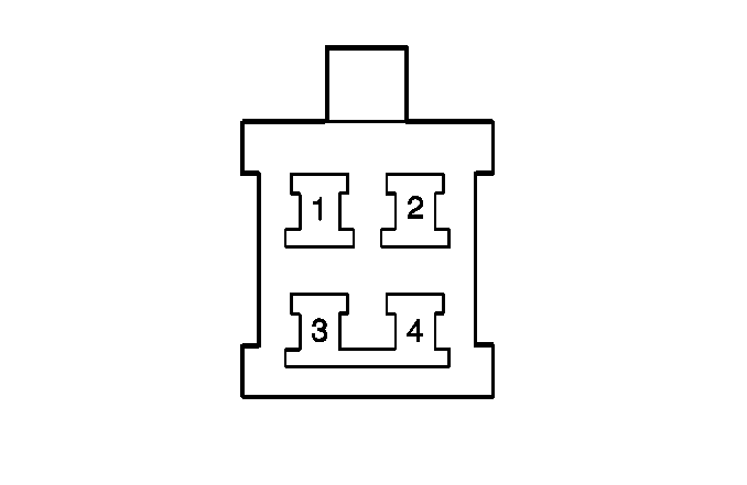
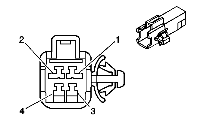
Pin | Wire Color | Function | Pin | Wire Color | Function | ||||||||
1 | BLK | Left Rear Speed Sensor High | 1 | BLK | Left Rear Speed Sensor High | ||||||||
2 | YEL | Left Rear Speed Sensor Low | 2 | YEL | Left Rear Speed Sensor Low | ||||||||
3 | RED | Right Rear Speed Sensor High | 3 | RED | Right Rear Speed Sensor High | ||||||||
4 | WHT | Right Rear Speed Sensor Low | 4 | WHT | Right Rear Speed Sensor Low | ||||||||

| |||||||||||||
|---|---|---|---|---|---|---|---|---|---|---|---|---|---|
Connector Part Information |
| Connector Part Information |
| ||||||||||
Pin | Wire Color | Function | Pin | Wire Color | Function | ||||||||
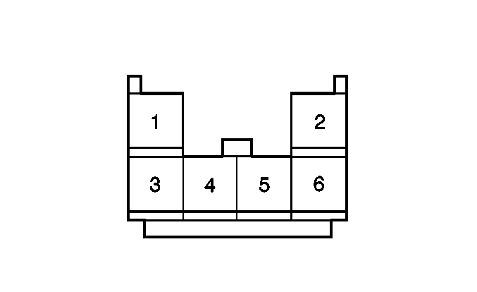
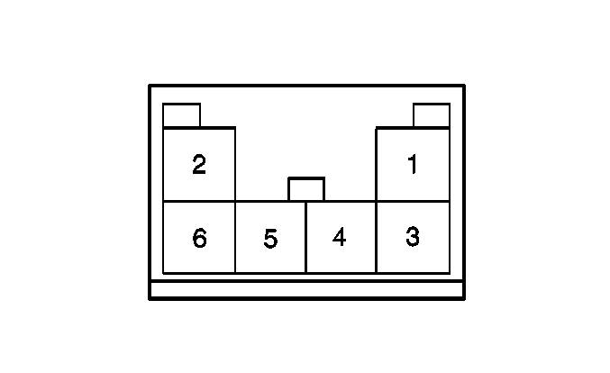
1 | -- | Not Used | 1 | -- | Not Used | ||||||||
2 | BLK | Positive Signal -- Speaker RF Door | 2 | BLK | Positive Signal -- Speaker RF Door | ||||||||
3 | RED/BLU | Left Rear Window Master Switch Up Supply Voltage | 3 | RED/BLU | Left Rear Window Master Switch Up Supply Voltage | ||||||||
4 | BLU | Left Rear Window Master Switch Down Supply Voltage | 4 | BLU | Left Rear Window Master Switch Down Supply Voltage | ||||||||
5 | -- | Not Used | 5 | -- | Not Used | ||||||||
6 | YEL | Left Rear Speaker Ground | 6 | YEL | Left Rear Speaker Ground | ||||||||
7 | -- | Not Used | 7 | -- | Not Used | ||||||||
8 | BLK | Rear Defogger Supply Voltage | 8 | BLK | Rear Defogger Supply Voltage | ||||||||
9 | RED/WHT | Ignition Positive Voltage -- Rear Wiper Diode | 9 | RED/WHT | Ignition Positive Voltage -- Rear Wiper Diode | ||||||||
10 | BLU | Ignition Positive Voltage | 10 | BLU | Ignition Positive Voltage | ||||||||
|
| ||||||||||||
|---|---|---|---|---|---|---|---|---|---|---|---|---|---|
Connector Part Information |
| Connector Part Information |
| ||||||||||
Pin | Wire Color | Function | Pin | Wire Color | Function | ||||||||
1 | BLK/WHT | Blower Motor High Voltage | 1 | BLK/WHT | Blower Motor High Voltage | ||||||||
2 | BLU/WHT | Blower Motor Medium 2 Voltage | 2 | LT BLU | Blower Motor Medium 2 Voltage | ||||||||
3 | BRN | Evaporator Temperature Sensor Ground | 3 | -- | Evaporator Temperature Sensor Ground | ||||||||
4 | BLK/BLU | Evaporator Temperature Sensor Input | 4 | -- | Evaporator Temperature Sensor Input | ||||||||
5 | WHT/BLK | Blower Motor Resistor Ground | 5 | WHT/BLK | Blower Motor Resistor Ground | ||||||||
6 | RED | Blower Motor Medium 1 Voltage | 6 | RED | Blower Motor Medium 1 Voltage | ||||||||

| |||||||||||||
|---|---|---|---|---|---|---|---|---|---|---|---|---|---|
Connector Part Information |
| Connector Part Information |
| ||||||||||
Pin | Wire Color | Function | Pin | Wire Color | Function | ||||||||
1 | BRN | Data Link Connector Ground | 1 | BRN | Data Link Connector Ground | ||||||||
2 | LT GRN/BLK | Park Neutral Position Switch Low Position Signal to PCM | 2 | LT GRN/BLK | Park Neutral Position Switch Low Position Signal to PCM | ||||||||
3 | BLU | Shift Solenoid S2 Signal | 3 | BLU | Shift Solenoid S2 Signal | ||||||||
4 | BLU | Park Neutral Position Switch Drive Position Signal to PCM | 4 | BLU | Park Neutral Position Switch Drive Position Signal to PCM | ||||||||
5 | LT GRN | Park Neutral Position Switch 2nd Position Signal to PCM | 5 | LT GRN | Park Neutral Position Switch 2nd Position Signal to PCM | ||||||||
6 | BLK | Battery Positive Voltage | 6 | BLK | Battery Positive Voltage | ||||||||
7 | BLK | Starter Supply Voltage | 7 | BLK | Starter Supply Voltage | ||||||||
8 | BLK/WHT | Ignition On Voltage -- Fuel Injector Supply Voltage | 8 | BLK/WHT | Ignition On Voltage -- Fuel Injector Supply Voltage | ||||||||
9 | BLK | Battery Positive Voltage | 9 | BLK | Battery Positive Voltage | ||||||||
10 | -- | Not Used | 10 | -- | Not Used | ||||||||

| |||||||||||||
|---|---|---|---|---|---|---|---|---|---|---|---|---|---|
Connector Part Information |
| Connector Part Information |
| ||||||||||
Pin | Wire Color | Function | Pin | Wire Color | Function | ||||||||
1-6 | -- | Not Used | 1-6 | -- | Not Used | ||||||||
7 | BLK/WHT | EFI Relay Control | 7 | BLK/WHT | EFI Relay Control | ||||||||
8 | BLU/WHT | Auxiliary Intake Air Solenoid Valve Control | 8 | BLU/WHT | Auxiliary Intake Air Solenoid Valve Control | ||||||||
9 | PNK | Heated Oxygen Sensor Heater Control | 9 | PNK | Heated Oxygen Sensor Heater Control | ||||||||
10-11 | -- | Not Used | 10-11 | -- | Not Used | ||||||||

|

| ||||||||||||
|---|---|---|---|---|---|---|---|---|---|---|---|---|---|
Connector Part Information |
| Connector Part Information |
| ||||||||||
Pin | Wire Color | Function | Pin | Wire Color | Function | ||||||||
1 | BRN | Sensor Ground | 1 | BRN | Sensor Ground | ||||||||
2 | YEL | Generator Charge Indicator Signal | 2 | YEL
| Generator Charge Indicator Signal | ||||||||
3 | WHT | Ground -- Oil Pressure Indicator | 3 | WHT | Ground -- Oil Pressure Indicator | ||||||||
4 | WHT/GRN | Speedometer -- Vehicle Speed Input | 4 | WHT/GRN | Speedometer -- Vehicle Speed Input | ||||||||
5 | BRN | Ground -- Instrument Panel Cluster | 5 | BRN | Ground -- Instrument Panel Cluster | ||||||||
6 | Braided | Drain | 6 | Braided | Drain | ||||||||
7 | BRN | Sensor Ground | 7 | BRN | Sensor Ground | ||||||||
8 | BRN | Ground -- Heated Oxygen Sensor 2 | 8 | BRN | Ground -- Heated Oxygen Sensor 2 | ||||||||
9 | Braided | Drain | 9 | Braided | Drain | ||||||||
10 | WHT/BLK | Ground -- PCM | 10 | WHT/BLK | Ground -- PCM | ||||||||
11 | BLK | Crank Signal--PCM | 11 | BLK | Crank Signal--PCM | ||||||||
12 | RED | Ignition Positive Voltage | 12 | RED | Ignition Positive Voltage | ||||||||
13 | RED/BLK | Park Neutral Position Switch Reverse Lamp Supply Voltage and Signal Input | 13 | RED/BLK | Park Neutral Position Switch Reverse Lamp Supply Voltage and Signal Input | ||||||||
14 | RED/WHT | Ignition ON Voltage | 14 | RED/WHT | Ignition ON Voltage | ||||||||
15 | RED | Heated Oxygen Sensor 1 Input | 15 | RED | Heated Oxygen Sensor 1 Input | ||||||||
16 | YEL | 5 Sensor Volt Reference Signal | 16 | YEL | 5 Sensor Volt Reference Signal | ||||||||
17 | BLU | EVAP Canister Vent Solenoid Valve Control | 17 | BLU | EVAP Canister Vent Solenoid Valve Control | ||||||||
18 | WHT | Heated Oxygen Sensor 2 Heater Control | 18 | WHT | Heated Oxygen Sensor 2 Heater Control | ||||||||

|

| ||||||||||||
|---|---|---|---|---|---|---|---|---|---|---|---|---|---|
Connector Part Information |
| Connector Part Information |
| ||||||||||
Pin | Wire Color | Function | Pin | Wire Color | Function | ||||||||
1 | GRN/YEL | Ambient Light Control Sensor Battery Voltage | 1 | GRN/YEL | Ambient Light Control Sensor Battery Voltage | ||||||||
2 | GRN/RED | Ambient Light Control Sensor Ground | 2 | GRN/WHT | Ambient Light Control Sensor Ground | ||||||||
3 | GRN/ORN | Ambient Light Control Sensor Signal | 3 | GRN/BLK | Ambient Light Control Sensor Signal | ||||||||

| |||||||||||||
|---|---|---|---|---|---|---|---|---|---|---|---|---|---|
Connector Part Information |
| Connector Part Information |
| ||||||||||
Pin | Wire Color | Function | Pin | Wire Color | Function | ||||||||
1-2 | -- | Not Used | 1-2 | -- | Not Used | ||||||||
3 | PPL | Left Rear Speaker Ground | 3 | PPL | Left Rear Speaker Ground | ||||||||
4 | PNK | Left Rear Speaker Positive | 4 | PNK | Left Rear Speaker Positive | ||||||||
5-7 | -- | Not Used | 5-7 | -- | Not Used | ||||||||
8 | LT GRN | Left Rear View Mirror Up/Down Signal | 8 | LT GRN | Left Rear View Mirror Up/Down Signal | ||||||||
9 | BRN/WHT | Left Rear View Mirror Up/Down Signal | 9 | BRN/WHT | Left Rear View Mirror Up/Down Signal | ||||||||
10 | BLU | Left Rear View Mirror Right/Left Signal | 10 | BLU | Left Rear View Mirror Right/Left Signal | ||||||||

| |||||||||||||
|---|---|---|---|---|---|---|---|---|---|---|---|---|---|
Connector Part Information |
| Connector Part Information |
| ||||||||||
Pin | Wire Color | Function | Pin | Wire Color | Function | ||||||||
1 | BLK | Left Front Power Window Switch Supply Voltage | 1 | BLK | Left Front Power Window Switch Supply Voltage | ||||||||
2 | -- | Not Used | 2 | -- | Not Used | ||||||||
3 | WHT | LH Front Key Switch Unlock Detection Signal | 3 | WHT | LH Front Key Switch Unlock Detection Signal | ||||||||
4 | BLU | Left Front Door Lock Switch Unlock Signal | 4 | BLU | Left Front Door Lock Switch Unlock Signal | ||||||||
5 | BLU/WHT | Left Front Door Lock Switch Lock Signal | 5 | BLU/WHT | Left Front Door Lock Switch Lock Signal | ||||||||
6 | WHT/BLK | Key Cylinder Switch Ground | 6 | WHT/BLK | Key Cylinder Switch Ground | ||||||||
7 | -- | Not Used | 7 | -- | Not Used | ||||||||
8 | RED | Left Front Door Lock Actuator Unlock Signal | 8 | RED | Left Front Door Lock Actuator Unlock Signal | ||||||||
9 | BLU | Left Front Door Lock Actuator Lock Signal | 9 | BLU | Left Front Door Lock Actuator Lock Signal | ||||||||
10 | BLU/YEL | Left Front Door Lock Actuator Unlock Signal | 10 | BLU/YEL | Left Front Door Lock Actuator Unlock Signal | ||||||||
11 | GRN | Left Front Door Lock Actuator Lock Signal | 11 | GRN | Left Front Door Lock Actuator Lock Signal | ||||||||
12 | -- | Not Used | 12 | -- | Not Used | ||||||||

| |||||||||||||
|---|---|---|---|---|---|---|---|---|---|---|---|---|---|
Connector Part Information |
| Connector Part Information |
| ||||||||||
Pin | Wire Color | Function | Pin | Wire Color | Function | ||||||||
1 | BLK/RED | Right Front Window Switch UP Signal | 1 | GRN/RED | Right Front Window Switch UP Signal | ||||||||
2 | BLK | Ignition Positive Voltage -- Master Power Window Switch | 2 | BLK | Ignition Positive Voltage -- Master Power Window Switch | ||||||||
3 | RED | Right Rear Window Switch Down Signal | 3 | BLU/RED | Right Rear Window Switch Down Signal | ||||||||
4 | RED/BLK | Right Rear Window Switch Up Signal | 4 | RED/BLK | Right Rear Window Switch Up Signal | ||||||||
5 | BLU | Left Rear Window Switch Down Signal | 5 | BLU | Left Rear Window Switch Down Signal | ||||||||
6 | RED/BLU | Left Rear Window Switch Up Signal | 6 | RED/GRN | Left Rear Window Switch Up Signal | ||||||||
7 | BLK/WHT | Right Front Window Switch Down Signal | 7 | BLU/WHT | Right Front Window Switch Down Signal | ||||||||

| |||||||||||||
|---|---|---|---|---|---|---|---|---|---|---|---|---|---|
Connector Part Information |
| Connector Part Information |
| ||||||||||
Pin | Wire Color | Function | Pin | Wire Color | Function | ||||||||
1 | WHT/BLK | Right Front Door Lock Actuator Key Cylinder Switch Ground | 1 | WHT/BLK | Right Front Door Lock Actuator Key Cylinder Switch Ground | ||||||||
2 | -- | Not Used | 2 | -- | Not Used | ||||||||
3 | WHT/RED | Right Front Door Lock Actuator Unlock Detection Signal -- Multifunction Alarm | 3 | WHT/RED | Right Front Door Lock Actuator Unlock Detection Signal -- Multifunction Alarm | ||||||||
4 | GRN/RED | Right Front Window Switch Up Voltage | 4 | GRN/RED | Right Front Window Switch Up Voltage | ||||||||
5 | BLU/WHT | Right Front Window Switch Down Voltage | 5 | BLU/WHT | Right Front Window Switch Down Voltage | ||||||||
6 | BLK | Right Front Power Window Switch Supply Voltage | 6 | BLK | Right Front Power Window Switch Supply Voltage | ||||||||
7 | BLU/WHT | Right Front Door Lock Switch Lock Signal | 7 | BLU/WHT | Right Front Door Lock Switch Lock Signal | ||||||||
8 | RED | Right Front Door Lock Actuator Unlock Signal -- Multifunction Alarm | 8 | RED | Right Front Door Lock Actuator Unlock Signal -- Multifunction Alarm | ||||||||
9 | BLU | Right Front Door Lock Actuator Lock Signal -- Multifunction Alarm | 9 | BLU | Right Front Door Lock Actuator Lock Signal -- Multifunction Alarm | ||||||||
10 | BLU/BLK | Right Front Door Lock Actuator Unlock Signal -- Key Switch | 10 | BLU/BLK | Right Front Door Lock Actuator Unlock Signal -- Key Switch | ||||||||
11 | GRN | Right Front Door Lock Actuator Lock Signal -- Key Switch | 11 | GRN | Right Front Door Lock Actuator Lock Signal -- Key Switch | ||||||||
12 | BLU | Right Front Door Lock Switch Unlock Signal -- Multifunction Alarm Module | 12 | BLU | Right Front Door Lock Switch Unlock Signal -- Multifunction Alarm Module | ||||||||

| |||||||||||||
|---|---|---|---|---|---|---|---|---|---|---|---|---|---|
Connector Part Information |
| Connector Part Information |
| ||||||||||
Pin | Wire Color | Function | Pin | Wire Color | Function | ||||||||
1-2 | -- | Not Used | 1-2 | -- | Not Used | ||||||||
3 | BLU | Right Front Speaker Ground | 3 | BLU | Right Front Speaker Ground | ||||||||
4 | LT GRN | Right Front Speaker Positive | 4 | LT GRN | Right Front Speaker Positive | ||||||||
5-7 | -- | Not Used | 5-7 | -- | Not Used | ||||||||
8 | RED/WHT | Right Rear View Mirror Up/Down Signal | 8 | RED/WHT | Right Rear View Mirror Up/Down Signal | ||||||||
9 | BRN/WHT | Right Rear View Mirror Up/Down Signal | 9 | BRN/WHT | Right Rear View Mirror Up/Down Signal | ||||||||
10 | RED | Right Rear View Mirror Up/Down Signal | 10 | RED | Right Rear View Mirror Up/Down Signal | ||||||||
|
| ||||||||||||
|---|---|---|---|---|---|---|---|---|---|---|---|---|---|
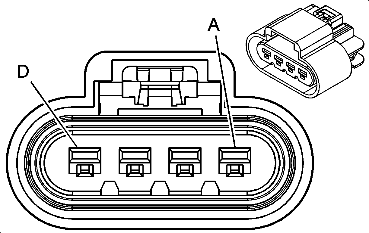
Connector Part Information |
| Connector Part Information |
| ||||||||||
Pin | Wire Color | Function | Pin | Wire Color | Function | ||||||||
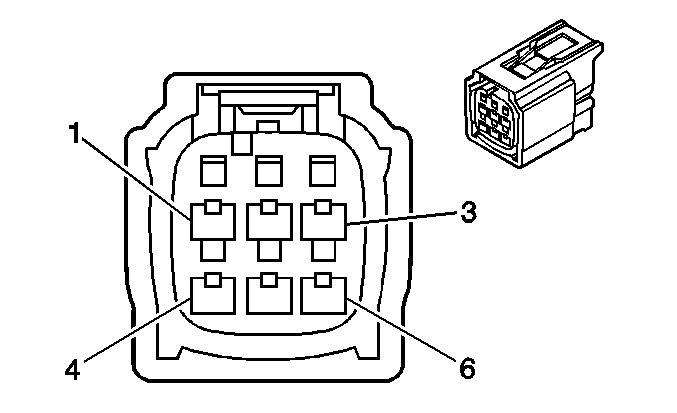
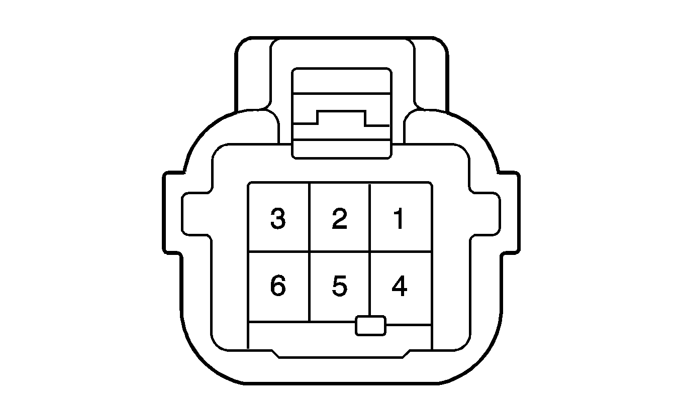
1 | WHT/BLK | Ground | 1 | BLK | Ground | ||||||||
2 | GRN | Driver Seat Belt Switch Signal | 2 | BLK/GRN | Driver Seat Belt Switch Signal | ||||||||
3 | GRN/YEL | Seat Belt Indicator Control | 3 | BLK/RED | Seat Belt Indicator Control | ||||||||
4 | GRN/WHT | Driver Seat Position High | 4 | YEL | Driver Seat Position High | ||||||||
5 | RED/BLK | Driver Seat Position Low | 5 | BLU | Driver Seat Position Low | ||||||||
6 | -- | Not Used | 6 | -- | Not Used | ||||||||
|
| ||||||||||||
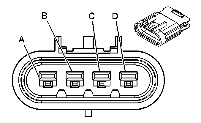
|---|---|---|---|---|---|---|---|---|---|---|---|---|---|
Connector Part Information |
| Connector Part Information |
| ||||||||||
Pin | Wire Color | Function | Pin | Wire Color | Function | ||||||||
A | WHT/BLK | Ground | A | BLK | Ground | ||||||||
B | BLK | Passenger Buckle Signal Circuit | B | BLK | Passenger Buckle Signal Circuit | ||||||||
C | BLU/WHT | Passenger Seat Occupant Detection Signal | C | BLK | Passenger Seat Belt warning Lamp Control Circuit | ||||||||
D | BLK | Passenger Buckle Signal Circuit | D | BLK | Passenger Buckle Signal Circuit | ||||||||
|
| ||||||||||||
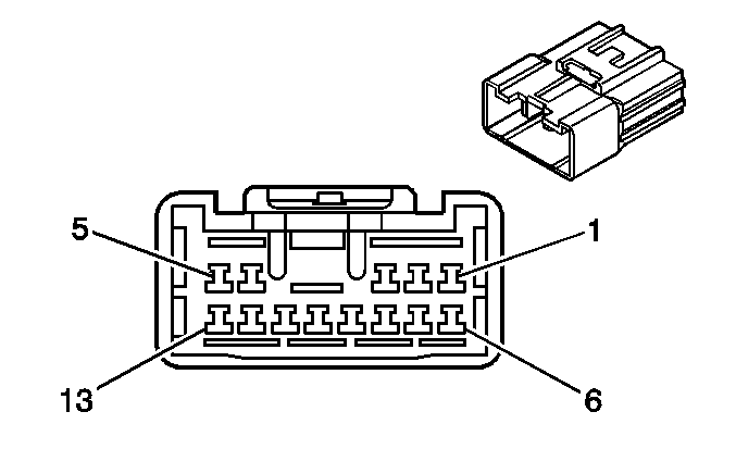
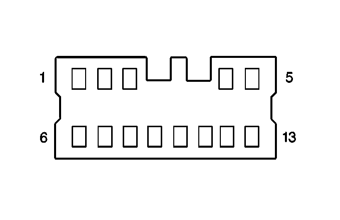
|---|---|---|---|---|---|---|---|---|---|---|---|---|---|
Connector Part Information |
| Connector Part Information |
| ||||||||||
Pin | Wire Color | Function | Pin | Wire Color | Function | ||||||||
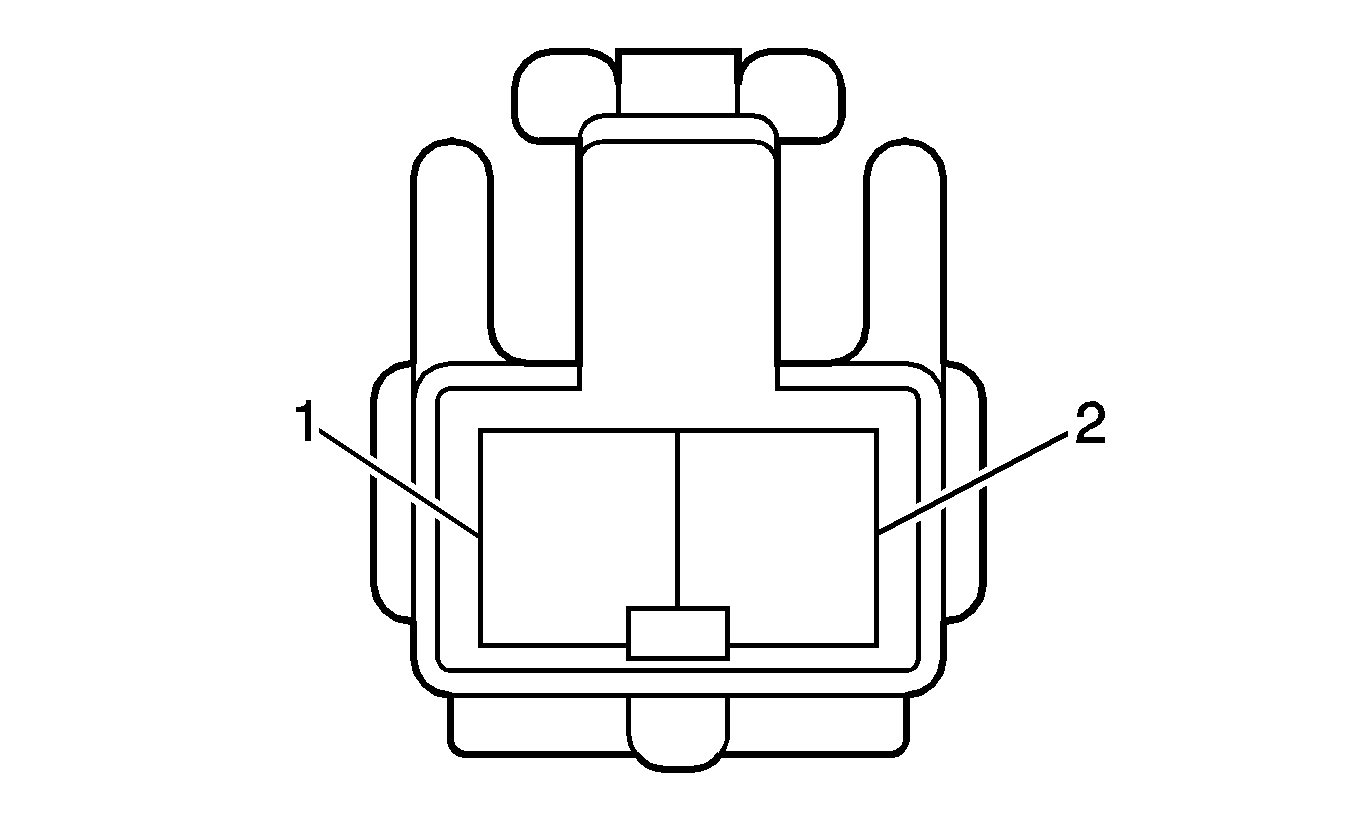
1 | BRN | Fuel Tank Pressure Sensor Ground | 1 | BRN | Fuel Tank Pressure Sensor Ground | ||||||||
2 | BLU | Fuel Tank Pressure Sensor Input | 2 | BLU | Fuel Tank Pressure Sensor Input | ||||||||
3 | WHT | Rear Glass Hatch Actuator Supply Voltage | 3 | WHT | Rear Glass Hatch Actuator Supply Voltage | ||||||||
4 | PNK | Rear Wiper Off Position Signal | 4 | PNK | Rear Wiper Off Position Signal | ||||||||
5 | YEL | Fuel Sender Assembly Fuel Gauge Signal | 5 | YEL | Fuel Sender Assembly Fuel Gauge Signal | ||||||||
6 | YEL | Fuel Tank Pressure Sensor 5 Volt Reference Voltage | 6 | YEL | Fuel Tank Pressure Sensor 5 Volt Reference Voltage | ||||||||
7 | BLK | EVAP Pressure Switching Solenoid Supply Voltage | 7 | BLK | EVAP Pressure Switching Solenoid Supply Voltage | ||||||||
8 | RED | EVAP Control -- PCM | 8 | RED | EVAP Control -- PCM | ||||||||
9-11 | -- | Not Used | 9-11 | -- | Not Used | ||||||||
12 | WHT | Rear Wiper ON Voltage | 12 | WHT | Rear Wiper ON Voltage | ||||||||
13 | BRN | Low Fuel Indicator Signal | 13 | BRN | Low Fuel Indicator Signal | ||||||||
|
| ||||||||||||
|---|---|---|---|---|---|---|---|---|---|---|---|---|---|
Connector Part Information |
| Connector Part Information |
| ||||||||||
Pin | Wire Color | Function | Pin | Wire Color | Function | ||||||||
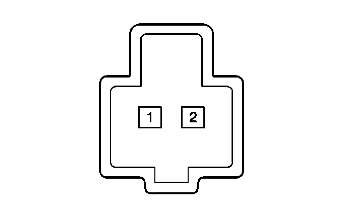
1 | BLU/YEL | Center Console Power Outlet | 1 | BLU/YEL | Center Console Power Outlet | ||||||||
2 | WHT/BLK | Center Console Power Outlet Ground | 2 | WHT/BLK | Center Console Power Outlet Ground | ||||||||

|

| ||||||||||||
|---|---|---|---|---|---|---|---|---|---|---|---|---|---|
Connector Part Information |
| Connector Part Information |
| ||||||||||
Pin | Wire Color | Function | Pin | Wire Color | Function | ||||||||
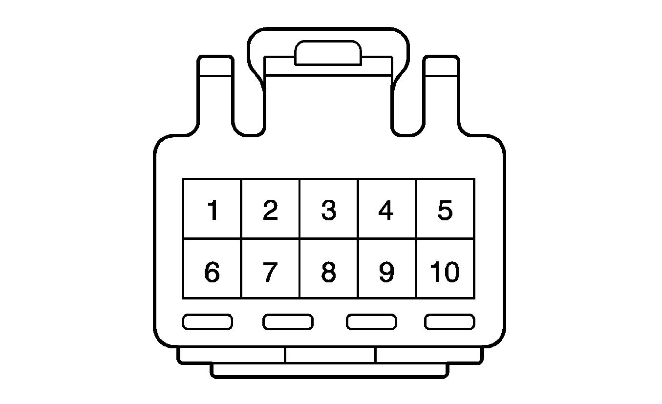
1 | GRN/ YEL | Drivers Seat Belt Indicator Signal | 1 | GRN/ YEL | Drivers Seat Belt Indicator Signal | ||||||||
2 | WHT/BLK | Drivers Seat Belt Switch Ground | 2 | WHT/BLK | Drivers Seat Belt Switch Ground | ||||||||
3 | BLU/WHT | Passengers Occupant Detection Sesor Signal | 3 | BLU/WHT | Passengers Occupant Detection Sesor Signal | ||||||||
4 | WHT/BLK | Drivers Seat Belt Switch Ground | 4 | WHT/BLK | Drivers Seat Belt Switch Ground | ||||||||
|
| ||||||||||||
|---|---|---|---|---|---|---|---|---|---|---|---|---|---|
Connector Part Information |
| Connector Part Information |
| ||||||||||
Pin | Wire Color | Function | Pin | Wire Color | Function | ||||||||
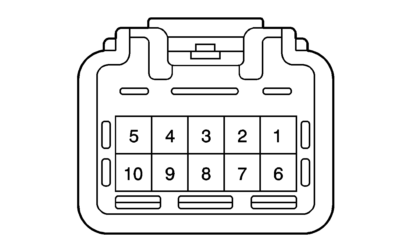
1 | -- | Not Used | 1 | -- | Not Used | ||||||||
2 | -- | Not Used | 2 | -- | Not Used | ||||||||
3 | BLK | Front Map Lamp Ground | 3 | BLK | Front Map Lamp Ground | ||||||||
4 | -- | Not Used | 4 | -- | Not Used | ||||||||
5 | -- | Not Used | 5 | -- | Not Used | ||||||||
6 | -- | Not Used | 6 | -- | Not Used | ||||||||
7 | -- | Not Used | 7 | -- | Not Used | ||||||||
8 | -- | Not Used | 8 | -- | Not Used | ||||||||
9 | -- | Not Used | 9 | -- | Not Used | ||||||||
10 | -- | Not Used | 10 | -- | Not Used | ||||||||

| |||||||||||||
|---|---|---|---|---|---|---|---|---|---|---|---|---|---|
Connector Part Information |
| Connector Part Information |
| ||||||||||
Pin | Wire Color | Function | Pin | Wire Color | Function | ||||||||
1 | BLU | Tailgate Door Lock Actuator Lock Signal | 1 | BLU | Tailgate Door Lock Actuator Lock Signal | ||||||||
2 | WHT | Rear Glass Hatch Supply Voltage | 2 | WHT | Rear Glass Hatch Supply Voltage | ||||||||
3 | PNK | Rear Wiper Park Position Supply Voltage | 3 | PNK | Rear Wiper Park Position Supply Voltage | ||||||||
4 | BLU | Rear Wiper Motor Supply Voltage | 4 | BLU | Rear Wiper Motor Supply Voltage | ||||||||
5 | -- | Not Used | 5 | -- | Not Used | ||||||||
6 | RED | Tailgate Door Lock Actuator Unlock Signal | 6 | RED | Tailgate Door Lock Actuator Unlock Signal | ||||||||
7 | -- | Not Used | 7 | -- | Not Used | ||||||||
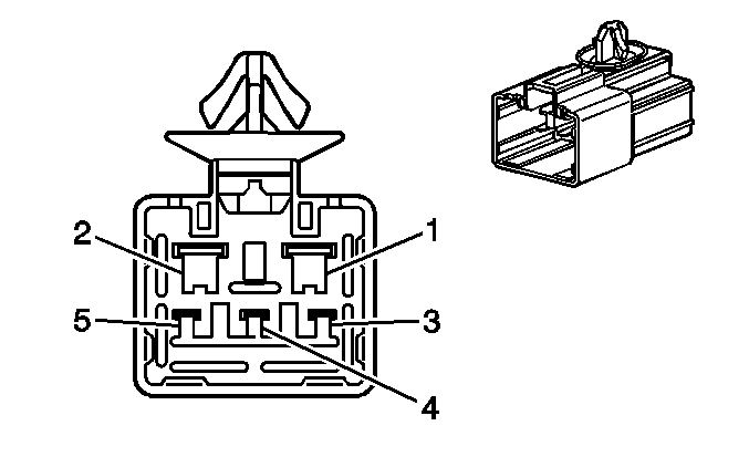
8 | WHT | Rear Wiper ON Position Supply Voltage | 8 | WHT | Rear Wiper ON Position Supply Voltage | ||||||||
9 | GRN/WHT | Center High Mounted Stop Lamp Supply Voltage | 9 | GRN/WHT | Center High Mounted Stop Lamp Supply Voltage | ||||||||
10 | WHT/BLK | Center High Mounted Stop Lamp Ground | 10 | WHT/BLK | Center High Mounted Stop Lamp Ground | ||||||||
|
| ||||||||||||
|---|---|---|---|---|---|---|---|---|---|---|---|---|---|
Connector Part Information |
| Connector Part Information |
| ||||||||||
Pin | Wire Color | Function | Pin | Wire Color | Function | ||||||||
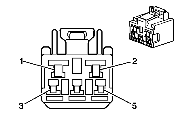
1 | BLK | Rear Defogger Supply Voltage | 1 | BLK | Rear Defogger Supply Voltage | ||||||||
2 | WHT/BLK | Glass Hatch Courtesy Switch Ground | 2 | WHT/BLK | Glass Hatch Courtesy Switch Ground | ||||||||
3 | RED/WHT | Rear Wiper Relay 1 Ground | 3 | RED/WHT | Rear Wiper Relay 1 Ground | ||||||||
4 | RED | Courtesy Lamps--Tailgate Signal | 4 | RED | Courtesy Lamps--Tailgate Signal | ||||||||
5 | GRN | Rear License Plate Lamp Supply Voltage | 5 | GRN | Rear License Plate Lamp Supply Voltage | ||||||||

| |||||||||||||
|---|---|---|---|---|---|---|---|---|---|---|---|---|---|
Connector Part Information |
| Connector Part Information |
| ||||||||||
Pin | Wire Color | Function | Pin | Wire Color | Function | ||||||||
1 | -- | Not Used | 1 | -- | Not Used | ||||||||
2 | BLK | Right Rear Window Switch Supply Voltage | 2 | BLK | Right Rear Window Switch Supply Voltage | ||||||||
3 | BLU | Right Rear Door Lock Actuator Lock Signal | 3 | BLU | Right Rear Door Lock Actuator Lock Signal | ||||||||
4 | RED/BLK | Right Rear Window Switch Up Voltage | 4 | RED/BLK | Right Rear Window Switch Up Voltage | ||||||||
5 | BLU/RED | Right Rear Window Switch Down Voltage | 5 | BLU/RED | Right Rear Window Switch Down Voltage | ||||||||
6 | WHT | Right Rear Door Speaker Ground | 6 | WHT | Right Rear Door Speaker Ground | ||||||||
7 | RED | Right Rear Door Speaker Positive | 7 | RED | Right Rear Door Speaker Positive | ||||||||
8 | RED | Right Rear Door Lock Actuator Unlock Signal | 8 | RED | Right Rear Door Lock Actuator Unlock Signal | ||||||||

| |||||||||||||
|---|---|---|---|---|---|---|---|---|---|---|---|---|---|
Connector Part Information |
| Connector Part Information |
| ||||||||||
Pin | Wire Color | Function | Pin | Wire Color | Function | ||||||||
1 | -- | Not Used | 1 | -- | Not Used | ||||||||
2 | BLK | Left Rear Window Switch Supply Voltage | 2 | BLK | Left Rear Window Switch Supply Voltage | ||||||||
3 | BLU | Left Rear Door Lock Actuator Lock Signal | 3 | BLU | Left Rear Door Lock Actuator Lock Signal | ||||||||
4 | RED/BLK | Left Rear Window Switch Up Voltage | 4 | RED/BLK | Left Rear Window Switch Up Voltage | ||||||||
5 | BLU/RED | Left Rear Window Switch Down Voltage | 5 | BLU/RED | Left Rear Window Switch Down Voltage | ||||||||
6 | WHT | Left Rear Door Speaker Ground | 6 | WHT | Left Rear Door Speaker Ground | ||||||||
7 | RED | Left Rear Door Speaker Positive | 7 | RED | Left Rear Door Speaker Positive | ||||||||
8 | RED | Left Rear Door Lock Actuator Unlock Signal | 8 | RED | Left Rear Door Lock Actuator Unlock Signal | ||||||||

|
| ||||||||||||
|---|---|---|---|---|---|---|---|---|---|---|---|---|---|
Connector Part Information |
| Connector Part Information |
| ||||||||||
Pin | Wire Color | Function | Pin | Wire Color | Function | ||||||||
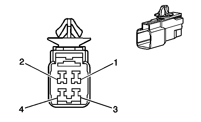
1 | RED/BLK | Left Rear Back Up Lamp Supply Voltage | 1 | RED/BLK | Left Rear Back Up Lamp Supply Voltage | ||||||||
2-3 | -- | Not Used | 2-3 | -- | Not Used | ||||||||
4 | WHT/BLK | Left Rear Back Up Lamp Ground | 4 | WHT/BLK | Left Rear Back Up Lamp Ground | ||||||||

|

| ||||||||||||
|---|---|---|---|---|---|---|---|---|---|---|---|---|---|
Connector Part Information |
| Connector Part Information |
| ||||||||||
Pin | Wire Color | Function | Pin | Wire Color | Function | ||||||||
1 | RED/BLK | Right Rear Back Up Lamp Supply Voltage | 1 | RED/BLK | Right Rear Back Up Lamp Supply Voltage | ||||||||
2-3 | -- | Not Used | 2-3 | -- | Not Used | ||||||||
4 | WHT/BLK | Right Rear Back Up Lamp Ground | 4 | WHT/BLK | Right Rear Back Up Lamp Ground | ||||||||
|
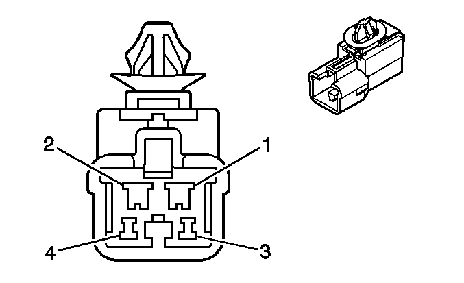
| ||||||||||||
|---|---|---|---|---|---|---|---|---|---|---|---|---|---|
Connector Part Information |
| Connector Part Information |
| ||||||||||
Pin | Wire Color | Function | Pin | Wire Color | Function | ||||||||
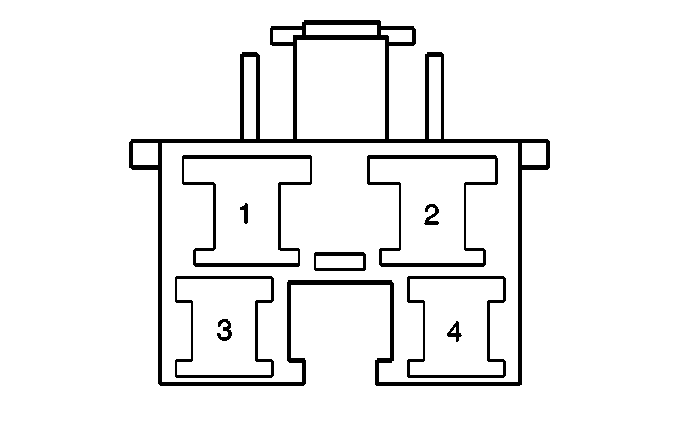
1 | BLK | Rear Defogger Supply Voltage | 1 | BLK | Rear Defogger Supply Voltage | ||||||||
2 | WHT/BLK | Rear Wiper Ground | 2 | WHT/BLK | Rear Wiper Ground | ||||||||
3 | BLU | Rear Wiper Supply Voltage | 3 | BLU | Rear Wiper Supply Voltage | ||||||||
4 | RED | Courtesy Lamp--Tailgate Signal | 4 | RED | Courtesy Lamp--Tailgate Signal | ||||||||

| |||||||||||||
|---|---|---|---|---|---|---|---|---|---|---|---|---|---|
Connector Part Information |
| Connector Part Information |
| ||||||||||
Pin | Wire Color | Function | Pin | Wire Color | Function | ||||||||
1 | BLU | Tailgate Door Lock Actuator Lock Signal | 1 | BLU | Tailgate Door Lock Actuator Lock Signal | ||||||||
2 | WHT | Glass Hatch Supply Voltage | 2 | WHT | Glass Hatch Supply Voltage | ||||||||
3 | GRN | Rear License Plate Lamp Supply Voltage | 3 | GRN | Rear License Plate Lamp Supply Voltage | ||||||||
4 | RED | Tailgate Door Unlock Actuator Lock Signal | 4 | RED | Tailgate Door Unlock Actuator Lock Signal | ||||||||
5 | -- | Not Used | 5 | -- | Not Used | ||||||||
6 | RED/WHT | Rear Wiper 1 Relay Ground | 6 | RED/WHT | Rear Wiper 1 Relay Ground | ||||||||
7 | WHT | Rear Wiper ON Position Supply Voltage | 7 | WHT | Rear Wiper ON Position Supply Voltage | ||||||||
8 | PNK | Rear Wiper Park Position Signal | 8 | PNK | Rear Wiper Park Position Signal | ||||||||
