Removal Procedure
- Remove the battery. Refer to Battery Replacement in Engine Electrical.
- Remove the 4 battery tray retaining bolts, then remove the battery tray from the vehicle.
- Remove the air cleaner case assembly.
- Remove the cruise control servo from the vehicle. Refer to Cruise Control Servo Replacement in Cruise Control.
- Remove the cylinder head cover from the engine. Refer to Cylinder Head Cover Removal in Engine Mechanical.
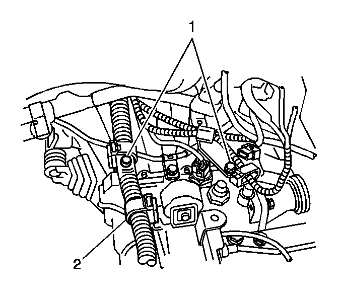
- Disconnect the wire harness (2) from the transaxle.
- Remove the 2 bolts, then disconnect the 2 wire harness brackets (1).
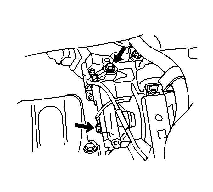
- Remove the 2 bolts and the ground cables from the transaxle.
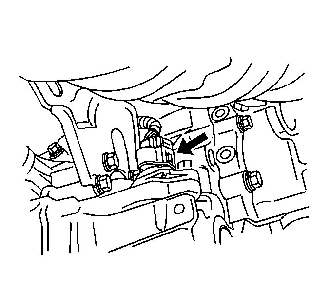
- Disconnect the backup lamp connector.
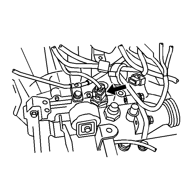
- Disconnect the vehicle speed sensor connector.
- Remove the clutch actuator cylinder and piping from the transaxle assembly.
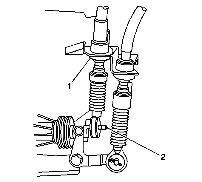
- Remove the clip and the washer (1), then disconnect the shift cable from the transaxle.
- Remove the clip (2), then disconnect the shift cable from the bracket.
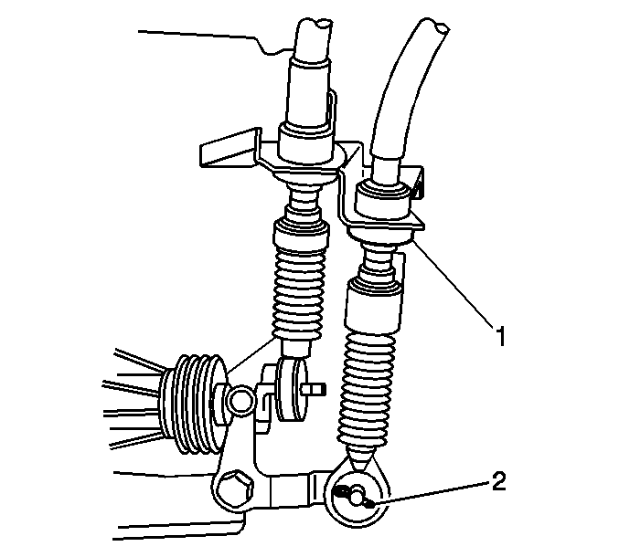
- Remove the clip and the washer (1), then disconnect the shift cable from the transaxle.
- Remove the clip (2), then disconnect the shift cable from the bracket.
- Remove the starter assembly from the vehicle. Refer to Starter Motor Replacement in Engine Electrical.
- Install the engine support fixture. Refer to Engine Support Fixture in Engine Mechanical.
- Raise the vehicle. Refer to Lifting and Jacking the Vehicle in General Information.
- Remove the front wheels. Refer to Tire and Wheel Removal and Installation in Tires and Wheels.
- Remove the left and right lower splash shields. Refer to Engine Splash Shield Replacement - Left Side and to Engine Splash Shield Replacement - Right Side in Body Front End.
- Remove the exhaust pipe from the vehicle. Refer to Catalytic Converter Replacement in Engine Exhaust.
- Remove the transaxle drain plug and the oil.
- Support the transaxle with a suitable jack.
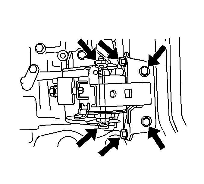
- Remove the 5 bolts from the left engine mount, then remove the mount from the vehicle.
- Remove the left and right drive shafts. Refer to Front Wheel Drive Shaft Replacement in Wheel Drive Shafts.
- Remove the front suspension cross-member. Refer to Front Suspension Crossmember Replacement in Frame and Underbody.
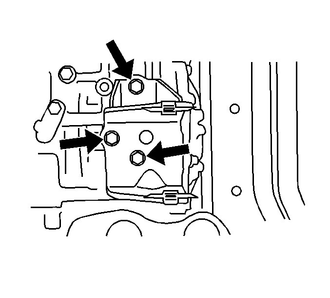
- Remove the 3 bolts from the left engine mount bracket, then remove the bracket from the vehicle.
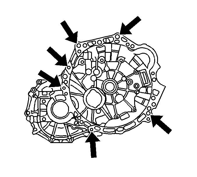
- Remove the 6 bolts that secure the transaxle to the engine mounting .
- Slightly lower the transaxle.
- Remove the transaxle from the engine.
Caution: Unless directed otherwise, the ignition and start switch must be in the OFF or LOCK position, and all electrical loads must be OFF before servicing any electrical component. Disconnect the negative battery cable to prevent an electrical spark should a tool or equipment come in contact with an exposed electrical terminal. Failure to follow these precautions may result in personal injury and/or damage to the vehicle or its components.
Installation Procedure
- Align the input shaft with the clutch disc and install the transaxle to the engine.
- Install the 6 bolts that secure the transaxle to the engine retaining.
- Install the left engine mounting bracket to the transaxle with the 3 bolts.
- Install the left engine mount with the 5 bolts and nuts.
- Lower the jack from the transaxle.
- Install the front suspension cross-member. Refer to Front Suspension Crossmember Replacement in Frame and Underbody.
- Install the left and right drive shafts. Refer to Front Wheel Drive Shaft Replacement in Wheel Drive Shafts.
- Install the left and right lower splash shields. Refer to Engine Splash Shield Replacement - Left Side and to Engine Splash Shield Replacement - Right Side in Body Front End.
- Install the exhaust pipe in the vehicle. Refer to Catalytic Converter Replacement in Engine Exhaust.
- Install the front wheels. Refer to Tire and Wheel Removal and Installation in Tires and Wheels.
- Install the drain plug with a new gasket.
- Install the fill plug with a new gasket.
- Fill the transaxle with 1.9L (2.0 qts) of API GL-4 or GL-5 SAE 75W-90 or equivalent.
- Lower the vehicle.
- Remove the engine support fixture.
- Install the starter assembly. Refer to Starter Motor Replacement in Engine Electrical.
- Connect the shift cable to the transaxle, then install the clip and washer (1).
- Connect the shift cable to the bracket, then install the clip (2).
- Connect the shift cable to the transaxle, then install the clip and washer (1).
- Connect the shift cable to the bracket, then install the clip (2).
- Install the clutch actuator cylinder and the piping.
- Connect the backup lamp connector.
- Connect the vehicle speed sensor connector.
- Connect the wire harness (2) from the transaxle.
- Connect the 2 wire harness brackets (1), then install the 2 bolts.
- Install the 2 bolts and the ground cables to the transaxle.
- Install the cruise control servo in the vehicle. Refer to Cruise Control Servo Replacement in Cruise Control.
- Install the battery tray and the 4 bolts.
- Install the battery. Refer to Battery Replacement in Engine Electrical.
- Install the air cleaner case assembly.
- Install the cylinder head cover on the engine. Refer to Cylinder Head Cover Replacement in Engine Mechanical.
Notice: Refer to Fastener Notice in the Preface section.
Tighten
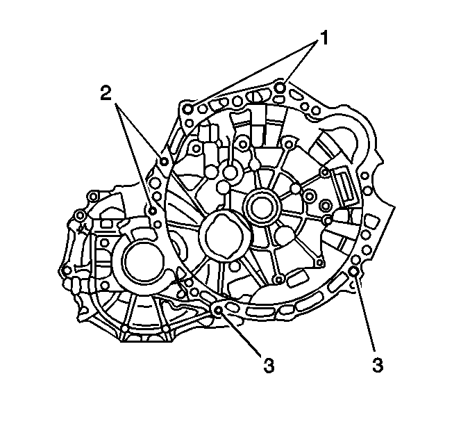
| • | Tighten the bolts (1) to 64 N·m (47 lb ft). |
| • | Tighten the bolt (2) to 46 N·m (35 lb ft). |
| • | Tighten the bolts (3) to 23 N·m (17 lb ft). |
Tighten
Tighten the bolts to 52 N·m (38 lb ft).
Tighten
| • | Tighten the bolts (1) to 52 N·m (38 lb ft). |
| • | Tighten the bolt (2) to 80 N·m (59 lb ft). |
Tighten
Tighten the drain plug to 39 N·m (29 lb ft).
Tighten
Tighten the fill plug to 39 N·m (29 lb ft).


Tighten
Tighten the bolts to 15 N·m (11 lb ft).

Tighten
Tighten the bolts to 13 N·m (10 lb ft).
Tighten
Tighten the bolts to 13 N·m (10 lb ft).
Caution: Unless directed otherwise, the ignition and start switch must be in the OFF or LOCK position, and all electrical loads must be OFF before servicing any electrical component. Disconnect the negative battery cable to prevent an electrical spark should a tool or equipment come in contact with an exposed electrical terminal. Failure to follow these precautions may result in personal injury and/or damage to the vehicle or its components.
