1992 SERVICE MANUAL UPDATE AUTOMATIC TRANSAXLE DIAGNOSIS

Subject: 1992 SERVICE MANUAL UPDATE - AUTOMATIC TRANSAXLE DIAGNOSIS SECTION
Models Affected: 1992 BONNEVILLE (M13), GRAND PRIX (ME9 AND (M13) AND TRANS SPORT (M13) MODELS
Bulletin Covers:
Updates to the 1992 Service Manual for the 4T60 and 4T60-E Automatic Transaxle Diagnosis Section. Mark a reference to this bulletin on your copy of the effected 1992 Service Manual.
Correction:
----------- (For Grand Prix models with 3.4L engine only)
The on-board computer in a vehicle with a 3.4L engine and Hydra-Matic 4T60-E transaxle that should be referred to is an ECM and not a PCM as published throughout the 1992 service manual:
SECTION/HYDRA-MATIC 4T60-E (GRAND PRIX EQUIPPED W/3.4L - DOHC ENGINE) AUTOMATIC TRANSAXLE DIAGNOSIS RPO (M13)
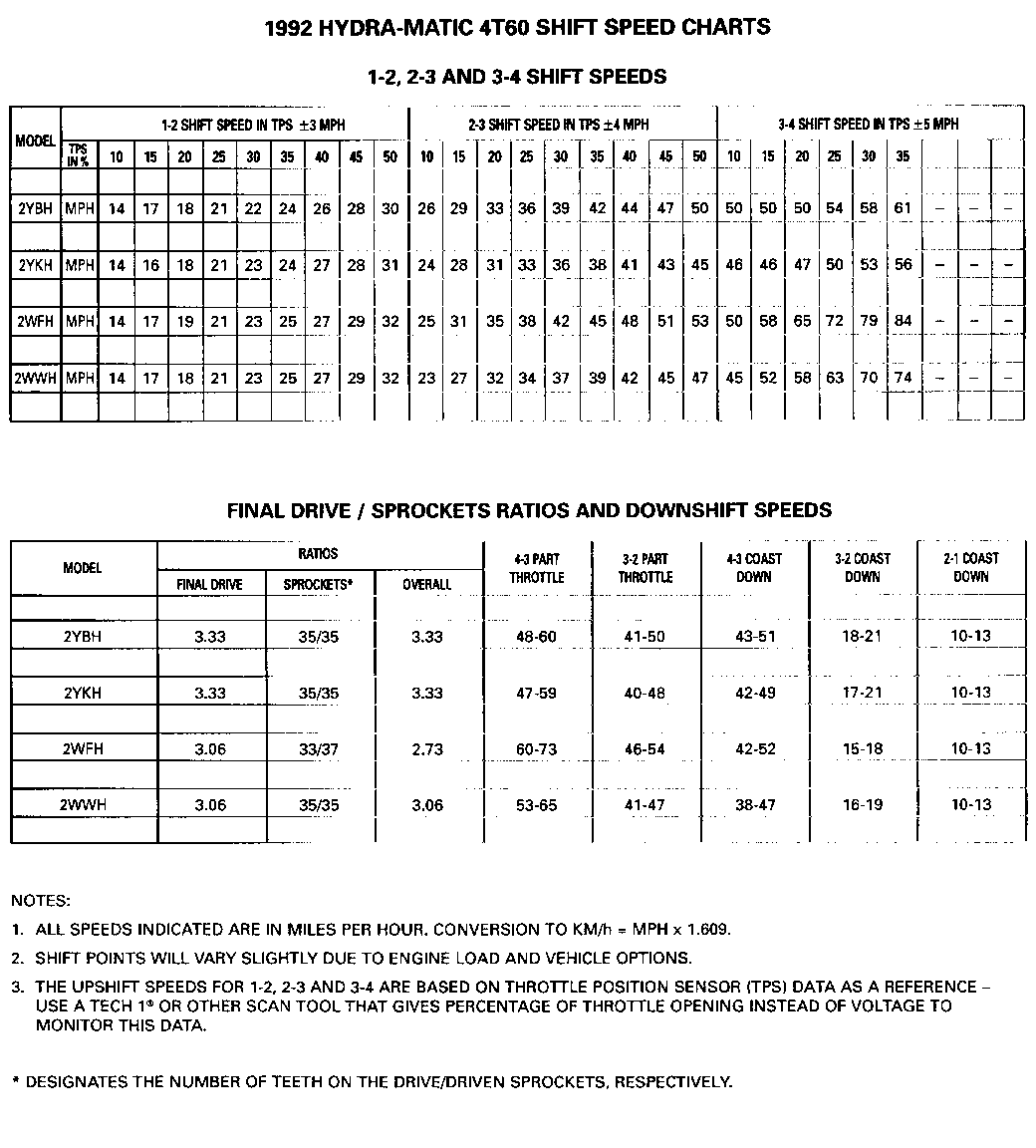
BULLETIN REVISED SERVICE MANUAL INFORMATION FIGURE FIGURE NUMBER FIGURE HEADING SECTION PAGE NUMBER ------- ---------------- -------------------- -------- ------ 7A HYDRA-MATIC 4T60 1 SHIFT SPEED AUTOMATIC TRANSAXLE 4T60-4 2 CHART (3.1 L. & 3800) DIAGNOSIS RPO (ME9)
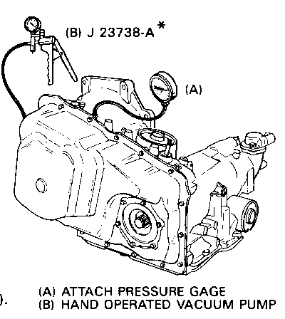
7A HYDRA-MATIC 4T60 2 LINE PRESSURE AUTOMATIC TRANSAXLE 4T60-5 3 CHECK DIAGNOSIS RPO (ME9)
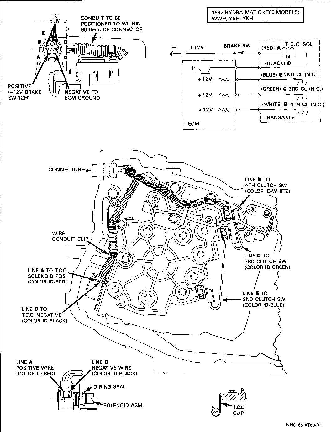
7A HYDRA-MATIC 4T60 3 WIRING AUTOMATIC TRANSAXLE 4T60-42 37 DIAGRAM DIAGNOSIS RPO (ME9)
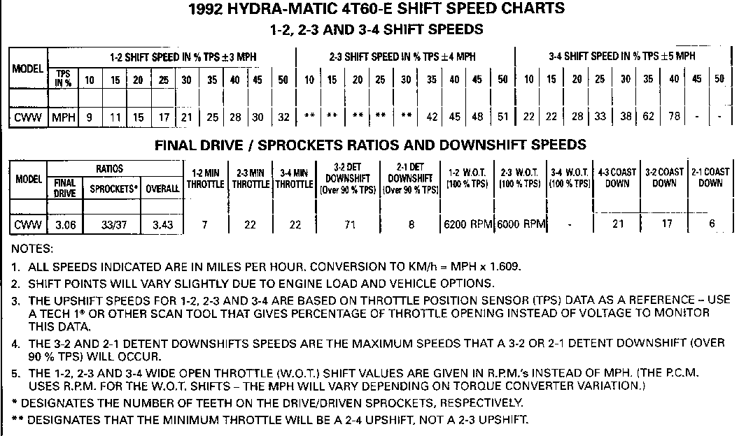
7A HYDRA-MATIC 4T60-E (W-CAR EQUIPPED WITH 4 SHIFT SPEED 3.4L. DOHC ENGINE) 4T60-E-5 3 CHART (3.4L.) AUTOMATIC TRANSAXLE DIAGNOSIS
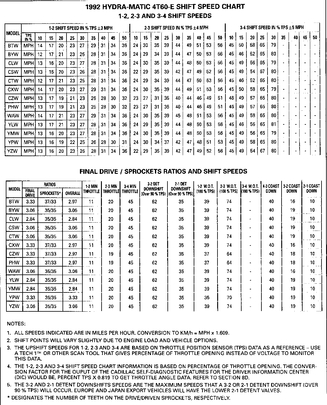
7A HYDRA-MATIC 4T60-E (WITH 3800 TPI 5 SHIFT SPEED [L27 & L67] ENGINE) 4T60-E-7 5 CHART (3800) AUTOMATIC TRANSAXLE DIAGNOSIS
7A HYDRA-MATIC 4T60-E 6 LINE PRESSURE (WITH 3800 TPI 4T60-E-20 11 [L27 & L671 ENGINE) CHECK PROCEDURE AUTOMATIC TRANSAXLE DIAGNOSIS
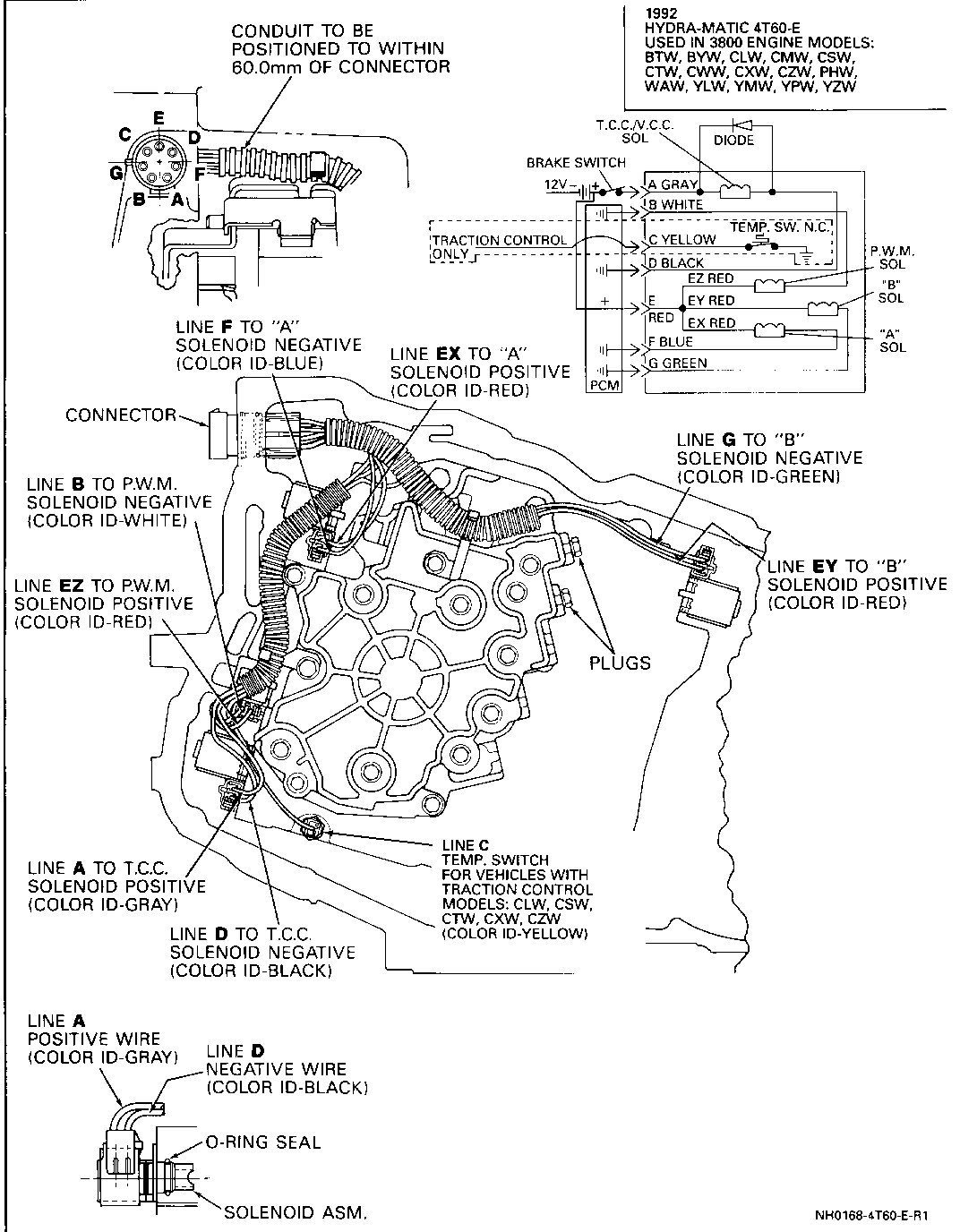
7A HYDRA-MATIC 4T60-E 7 WIRING (WITH 3800 TPI 4T60-E-30 21 DIAGRAM [L27 & L671 ENGINE) AUTOMATIC TRANSAXLE DIAGNOSIS
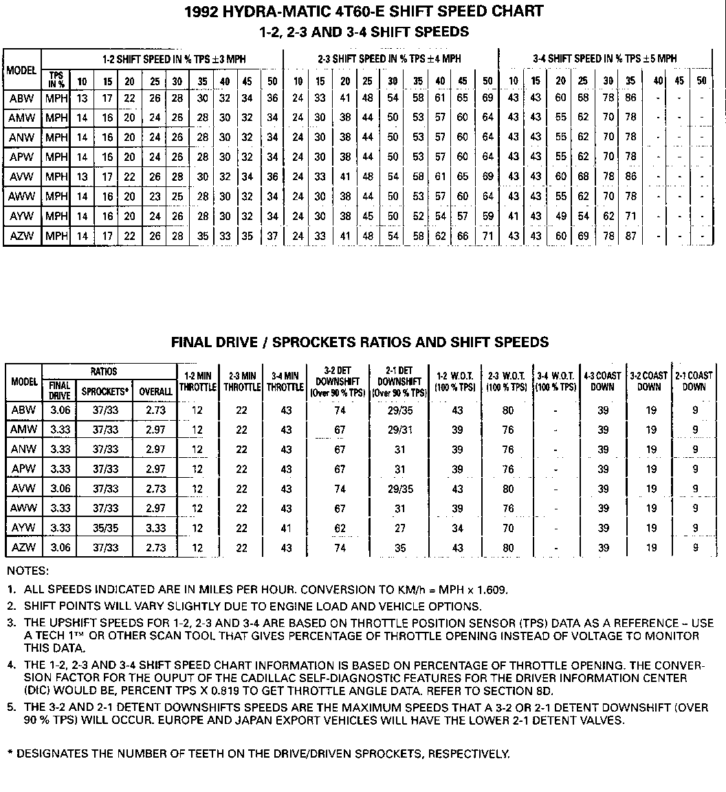
7A HYDRA-MATIC 4T60-E 8 SHIFT SPEED (C/E/K CAR EQUIPPED 4T60-E-5 3 CHART (4.9L.) WITH 4.9L PFI ENGINE) AUTOMATIC TRANSAXLE DIAGNOSIS
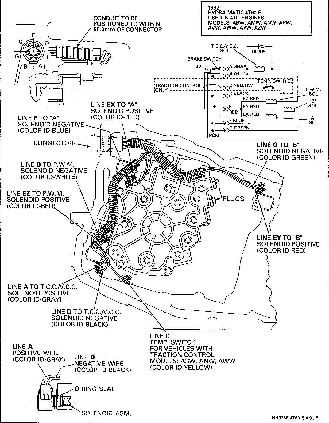
7A HYDRA-MATIC 4T60-E 9 WIRING (C/E/K CAR EQUIPPED 4T60-E-27 17 WITH 4.9L. PFI ENGINE) DIAGRAM AUTOMATIC TRANSAXLE DIAGNOSIS
LINE PRESSURE CHECK:
Line pressure is controlled by pump output to the pressure regulator valve and is boosted in Reverse and D1 by the reverse boost valve.
Also, line pressures should increase with throttle opening due to a decrease in engine vacuum supply to the vacuum modulator.
Line pressures will boost to a maximum pressure if the T.V. cable is disconnected at the throttle body and pulled to its full travel. This method of checking pressures WILL NOT provide accurate line pressure as referenced in the chart below.
CHECK PRESSURES IN THE FOLLOWING MANNER:
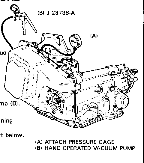
Minimum Line Pressure Check o Disconnect and plug vacuum supply at modulator. o Apply 61 kPa (18 in. Hg.) vacuum to modulator with pump (B). o Set parking brake and apply vehicle brakes. o Take pressure readings in all gear ranges with engine running at proper R.P.M. o Compare pressures with information provided in the chart below.
Full Line Pressure Check
o Have 0 kPa (0 in. Hg.) vacuum to modulator. o Set parking brake and apply vehicle brakes. o Take pressure readings in all gear ranges with engine running at proper R.P.M. o Compare pressures with information provided in the chart below.
NOTICE: Total running time not to exceed 2 minutes. CAUTION: Brakes must be applied at all times.
1992 HYDRA-MATIC 4T60 TRANSAXLE MODELS
WFH, WWH, YBH, YKH
RANGE kPa PSI --------- ---------- ----------- MINIMUM LINE D4,D3,D2 422 - 475 61 - 69 @ 1250 R.P.M. D1 998 - 1276 145 - 185 61 kPa (18 in. Hg.) P,R,N 422 - 551 61 - 80 Vacuum At Modulator
FULL LINE D4,D3,D2 1152 - 1393 167 - 202 @ 1250 R.P.M. D1 998 - 1276 145 - 185 0 kPa (0 In. Hg.) P,R,N 1573 - 1901 228 - 277 Vacuum At Modulator
LINE PRESSURE CHECK PROCEDURE
Line pressure is controlled by pump output to the pressure regulator valve and is boosted in Park, Reverse, Neutral and D1 by the reverse boost valve.
Also, line pressures should increase with throttle opening d to a decrease in engine vacuum supply to the vacuum modulator.
CHECK PRESSURES IN THE FOLLOWING MANNER:
Minimum Line Pressure Check o Disconnect and plug vacuum supply at modulator. o Apply 61 kPa (1 8 in. Hg.) vacuum to modulator with pump o Set parking brake and apply vehicle brakes. o Take pressure readings in all gear ranges with engine running at proper R.P.M. o Compare pressures with information provided in the chart below.
Full Line Pressure Check o Have 0 kPa (0 in. Hg.) vacuum to modulator. o Set parking brake and apply vehicle brakes. o Take pressure readings in all gear ranges with engine running at proper R.P.M. o Compare pressures with information provided in the chart below.
NOTICE: Total running time not to exceed 2 minutes. CAUTION: Brakes must be applied at all times
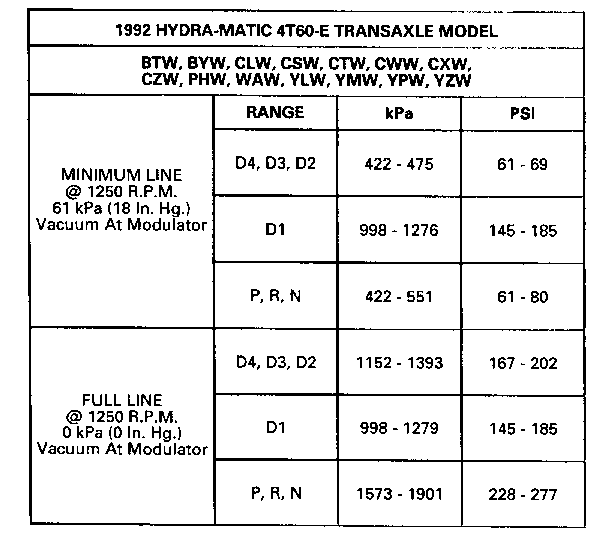
1992 HYDRA-MATIC 4T60-E TRANSAXLE MODEL
BTW, BYW, CLW, CSW, CTW, CWW, CXW, CZW, PHW, WAW, YLW, YMW, YPW, YZW
RANGE kPa PSI ---------- --------- --------- MINIMUM LINE D4, D3, D2 422 - 475 61 - 69 @ 1250 R.P.M. D1 998 -1276 145 - 185 61 kPa (18 in. Hg.) P, R, N 422 - 551 61 - 80 Vacuum At Modulator
FULL LINE D4, D3, D2 1152 - 1393 167 - 202 @ 1250 R.P.M. D1 998 - 1279 145 - 185 0 kPa (0 In. Hg.) P, R, N 1573 -1901 228 - 277 Vacuum At Modulator
General Motors bulletins are intended for use by professional technicians, not a "do-it-yourselfer". They are written to inform those technicians of conditions that may occur on some vehicles, or to provide information that could assist in the proper service of a vehicle. Properly trained technicians have the equipment, tools, safety instructions and know-how to do a job properly and safely. If a condition is described, do not assume that the bulletin applies to your vehicle, or that your vehicle will have that condition. See a General Motors dealer servicing your brand of General Motors vehicle for information on whether your vehicle may benefit from the information.
