SERVICE MANUAL UPDATE-SEC. 3B (POWER STEERING PUMP REPAIRS)

SUBJECT: SERV. MAN. UPDATE - SECTION 3B "STEERING" POWER STEERING PUMP UNIT REPAIR (SUPPLEMENTAL PROCEDURE)
VEHICLES AFFECTED: 1991 OPTIMA "T"
The information contained in this bulletin supplements the "Power Steering Pump Unit Repair" in SECTION 3Bl of the 1991 Optima Service Manual (S-9110-T).
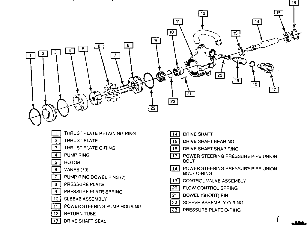
POWER STEERING PUMP ASSEMBLY - Refer to Figure 1
POWER STEERING PUMP UNIT REPAIR - Figures 1 through 19
Remove or Disconnect
Tools Required:
J 38343 Power Steering Drive Pulley Remover J 25033-B Power Steering Pump Pulley Installer J 23907 Slide Hammer
1. Power steering pump assembly from vehicle. Refer to SECTION 3Bl of the 1992 Optima Service Manual (S-9110-T).
2. Three bolts and power steering pump drive pulley from pulley hub.
* Mount power steering pump assembly into a vise with pulley hub facing up.
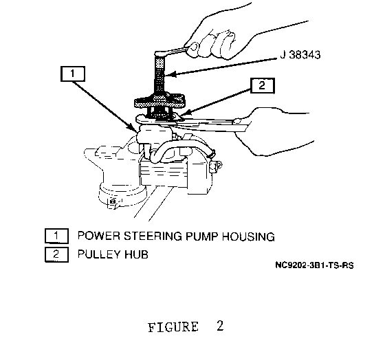
3. Pulley hub from power steering pump using a J 38343, as shown in Figure 2.
REMOVING PULLEY HUB
4. Pump assembly from vise, invert and remount into vise with thrust plate facing up.
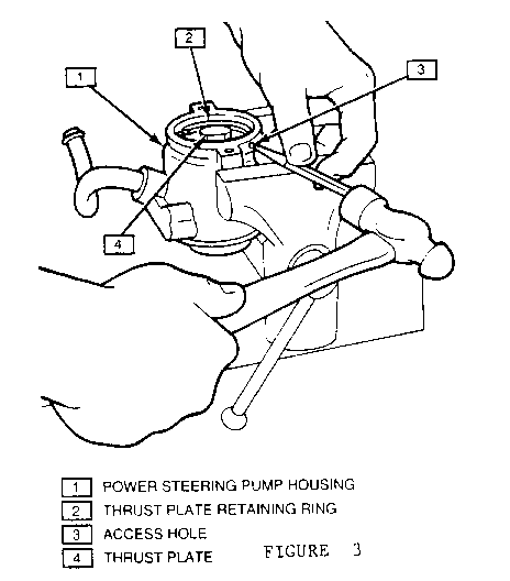
5. Thrust plate retaining ring, using a drift punch and a hammer. Insert the drift punch into the access hole and drive the retaining ring out of the power steering pump housing Refer to Figure 3.
REMOVING THRUST PLATE RETAINING RING
6. Pump assembly from vise, invert and remount into vise with drive shaft facing up.
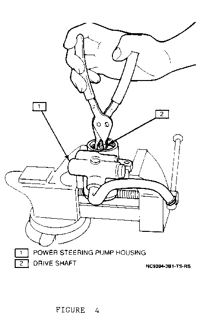
7. Drive shaft snap ring using snap ring pliers Refer to Figure 4.
REMOVING DRIVE SHAFT SNAP RING
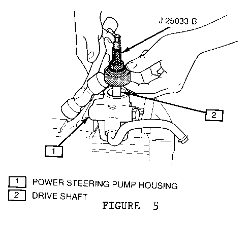
REMOVING DRIVE SHAFT AND FRONT BEARING
8. Drive shaft and drive shaft bearing from pump assembly using a J 25033-B and a rubber mallet Refer to Figure 5.
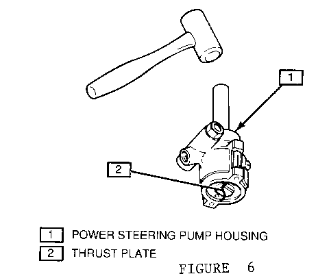
* Scribe matchmarks between the thrust plate and power steering pump housing.
* Loosen thrust plate from pump housing using a 1/4-inch drift punch and a hammer Refer to Figure 6. Do not remove thrust plate from housing.
LOOSENING THRUST PLATE
IMPORTANT
*To prevent the pump ring, rotor and vanes from falling out of the power steering pump housing and thus inhibiting proper reassembly, do not remove the thrust plate until the housing is inverted.
9. Pump assembly from vise, invert and remount into vise with thrust plate facing up.
10. Thrust plate from power steering pump housing.
11. Thrust plate 0-ring from power steering pump housing.
IMPORTANT
* Note the pump ring position relative to the power steering pump housing to ease pump reassembly.
12. Pump ring, two pump ring dowel pins, rotor and vanes from power steering pump housing.
* Scribe matchmarks between the pressure plate fluid passage and the power steering pump housing.
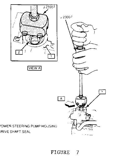
13. Pump assembly from vise, invert and reinstall into vise with drive shaft seal facing up.
14. Drive shaft seal using a i 23907 Refer to Figure 7.
REMOVING DRIVE SHAFT SEAL
15. Pump assembly from vise.
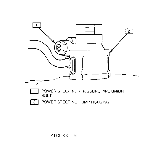
16. Pressure plate and pressure plate spring from power steering pump housing using a piece of 5/8-inch bar stock and a press Refer to Figure 8 . Remove 0-ring from pressure plate.
REMOVING PRESSURE PLATE
* Mount pump assembly into vise with thrust plate side facing up.
17. Dowel (short) pin from power steering pump housing.
18. Pump assembly from vise, invert and remount into vise with drive shaft side of pump facing up.
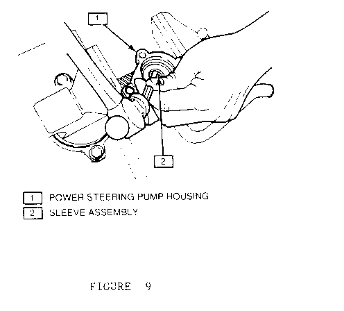
19. Sleeve assembly from power steering pump housing using a drift punch and a hammer Refer to Figure 9. Remove 0-ring from sleeve assembly.
REMOVING SLEEVE ASSEMBLY
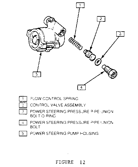
20. Power steering pressure pipe union bolt, control valve assembly and flow control spring from power steering pump housing. Remove 0-ring from union bolt.
* Scribe matchmarks between the return tube and the power steering pump housing.
21. Return tube from power steering pump housing; twist to break seal and pull tube from housing.
DISASSEMBLE
* Drive shaft bearing from drive shaft.
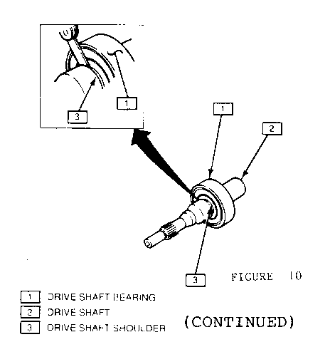
A. Using a feeler gage, measure and record the drive shaft bearing-to-drive shaft shoulder clearance Refer to Figure 10.
MEASURING DRIVE SHAFT BEARING-TO-DRIVE SHAFT SHOULDER CLEARANCE
B. Using a press, remove the drive shaft bearing from the drive shaft.
CLEAN
* Sealant from return tube and power steering pump housing.
ASSEMBLE
* Drive shaft bearing to drive shaft.
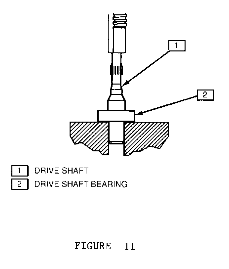
A. Using a press, install the drive shaft bearing to the drive shaft Refer to Figure 11.
INSTALLING DRIVE SHAFT BEARING
B. Using a feeler gauge, measure the drive shaft bearing-to-drive shaft shoulder clearance Refer to Figure 10. The clearance must be equal to the measurement taken prior to drive shaft bearing removal.
INSTALL or CONNECT
Tools Required:
J 7079-2 Driver Handle J 22670 Shaft Oil Seal Installer J 25033-B Power Steering Pump Pulley Installer
* Apply Loctite pipe sealant GM P/N 1052080, or equivalent, to return tube-to-power steering pump housing fitting.
1. Return tube to power steering pump housing aligning matchmarks; tap lightly with a rubber mallet to seat.
2. Flow control spring, control valve assembly and power steering pressure pipe union bolt, with new 0-ring, to power steering pump housing. Coat 0-ring with power steering gear and pump fluid GM P/N 1050017, or equivalent, prior to installation.
NOTICE: THE CONTROL VALVE ASSEMBLY MUST BE PROPERLY ORIENTED FOR PROPER INSTALLATION TO PREVENT DAMAGE TO THE POWER STEERING PUMP. REFER TO FIGURE 12 FOR PROPER CONTROL VALVE ASSEMBLY INSTALLATION.
INSERT FIGURE 12 PROPER CONTROL VALVE ASSEMBLY INSTALLATION
TIGHTEN
* Power steering pressure pipe union bolt to 75 N.m (55 ft.lbs.).
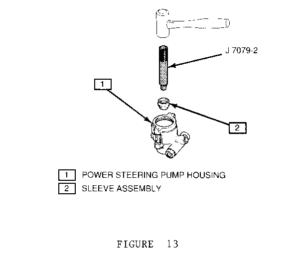
3. Sleeve assembly, with new 0-ring, to power steering pump housing using a J 7079-2 and a rubber mallet Refer to Figure 13. Tap lightly to seat.
INSTALLING SLEEVE ASSEMBLY
* Remove pump assembly from vise, invert and remount into vise with drive shaft side of pump facing down.
4. Dowel (short) pin to power steering pump housing.
5. New 0-ring to pressure plate. Coat 0-ring with power steering gear and pump fluid GM P/N 1050017, or equivalent.
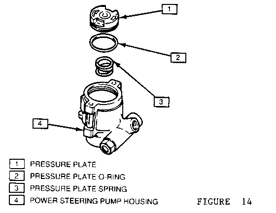
6. Pressure plate spring and pressure plate to power steering pump housing aligning matchmarks, as shown in Figure 14.
PRESSURE PLATE AND PRESSURE PLATE SPRING
7. Two pump ring dowel pins to holes in pressure plate.
8. Pump ring to power steering pump housing.
IMPORTANT
* Make sure that the pump ring is properly aligned in the pump housing.
9. Rotor to power steering pump housing.
IMPORTANT
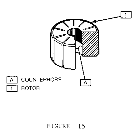
* The rotor must be installed with the counterbore facing the drive shaft end of the housing Refer to Figure 15.
PROPER ROTOR INSTALLATION
10. Vanes to rotor. Apply power steering gear and pump fluid GM P/N 1050017, or equivalent, to a new thrust plate 0-ring.
11. New thrust plate 0-ring to power steering pump housing.
12. Thrust plate and retaining ring to power steering pump housing; align thrust plate-to-housing matchmarks.
* Remove pump assembly from vise.
* Using a press, seat thrust plate into power steering pump housing; secure with retaining ring Refer to Figure 16.
INSTALLING THRUST PLATE AND RETAINING RING
* Mount pump assembly into vise with drive shaft side facing up.
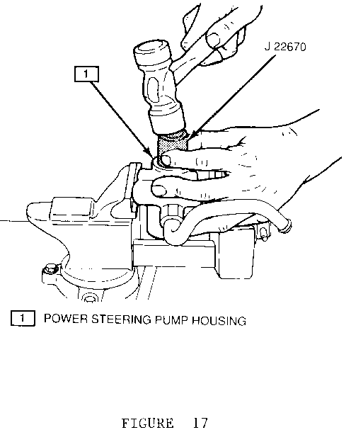
13. Drive shaft seal to power steering pump housing using a i 22670 and a hammer Refer to Figure 17.
INSTALLING DRIVE SHAFT.SEAL
* Coat drive shaft with power steering gear and pump fluid GM P/N 1050017, or equivalent.
* Using a pick, or other suitable tool, centre the rotor inside the pump ring.
14. Drive shaft to power steering pump housing; rotate the drive shaft to mesh the gear teeth with the rotor.
* Seat the drive shaft using a 30 mm socket and a hammer.
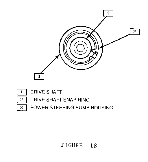
15. Drive shaft snap ring with the flat side towards the drive shaft bearing Refer to Figure 18.
PROPER DRIVE SHAFT SNAP RING INSTALLATION
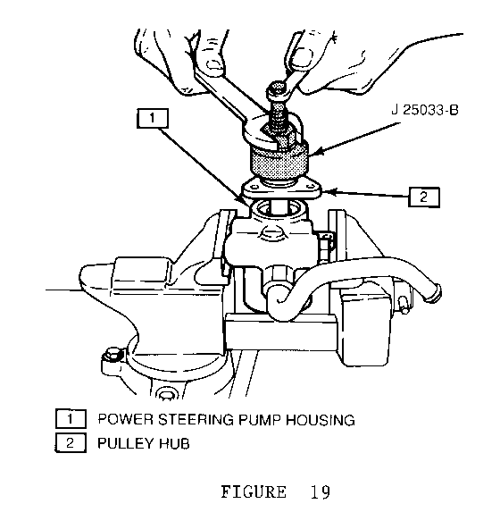
INSTALLING PULLEY HUB
16. Pulley hub to power steering pump assembly using a J 25033-B Refer to Figure 19
* Remove pump assembly from vise.
17. Power steering pump drive pulley to pulley hub; secure with three bolts.
TIGHTEN
* Power steering pump drive pulley bolts to 20 N.m (15 ft.lbs.).
18. Power steering pump assembly to vehicle.
Please note this change in your copies of the appropriate Service Manual.

General Motors bulletins are intended for use by professional technicians, not a "do-it-yourselfer". They are written to inform those technicians of conditions that may occur on some vehicles, or to provide information that could assist in the proper service of a vehicle. Properly trained technicians have the equipment, tools, safety instructions and know-how to do a job properly and safely. If a condition is described, do not assume that the bulletin applies to your vehicle, or that your vehicle will have that condition. See a General Motors dealer servicing your brand of General Motors vehicle for information on whether your vehicle may benefit from the information.
