For 1990-2009 cars only
Removal Procedure
- Disconnect the battery negative cable. Refer to Battery Negative Cable Disconnection and Connection .
- Remove the instrument panel (I/P) trim pad. Refer to Instrument Panel Trim Pad Replacement .
- Remove the bolt from the accessory wiring junction block.
- Disengage the junction block tabs from the passenger knee bolster. Remove the junction block from the knee bolster.
- Remove the booster push rod from the brake pedal.
- Remove the brake pedal bolt. Remove the brake pedal.
- Remove the brake pedal brace bolts from the I/P carrier cross car beam.
- Lower the body control module (BCM) away from the I/P carrier.
- Disconnect any ground wires, as necessary.
- Reposition the I/P wiring harness out of the way.
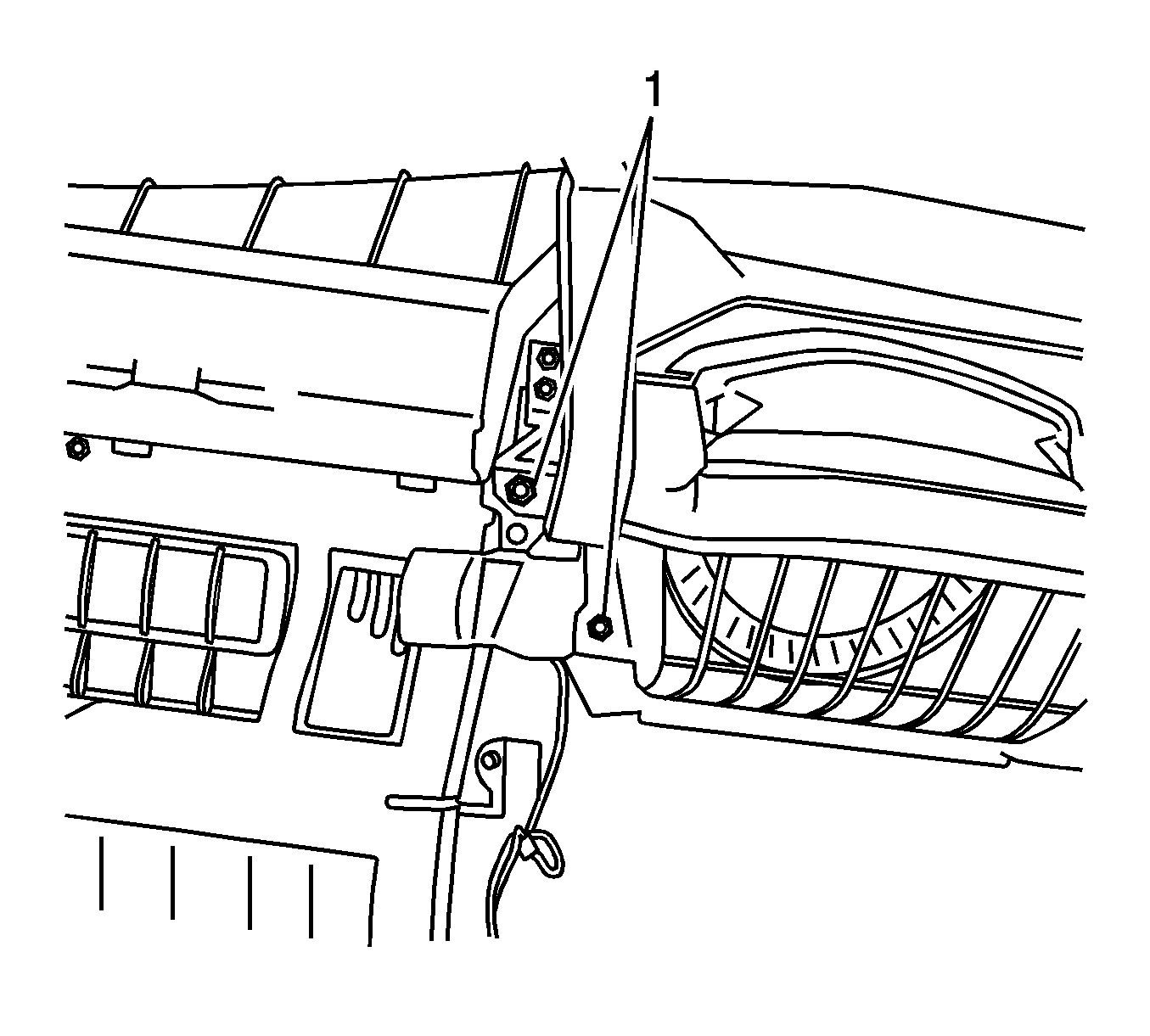
- Remove the bracket bolts from the HVAC module assembly lower support (1).
- Remove the bracket bolts from the HVAC module assembly RH support (2).
- Remove the bracket bolts from the HVAC module upper support
- Remove the right and the left I/P carrier bolts.
- Remove the I/P carrier.
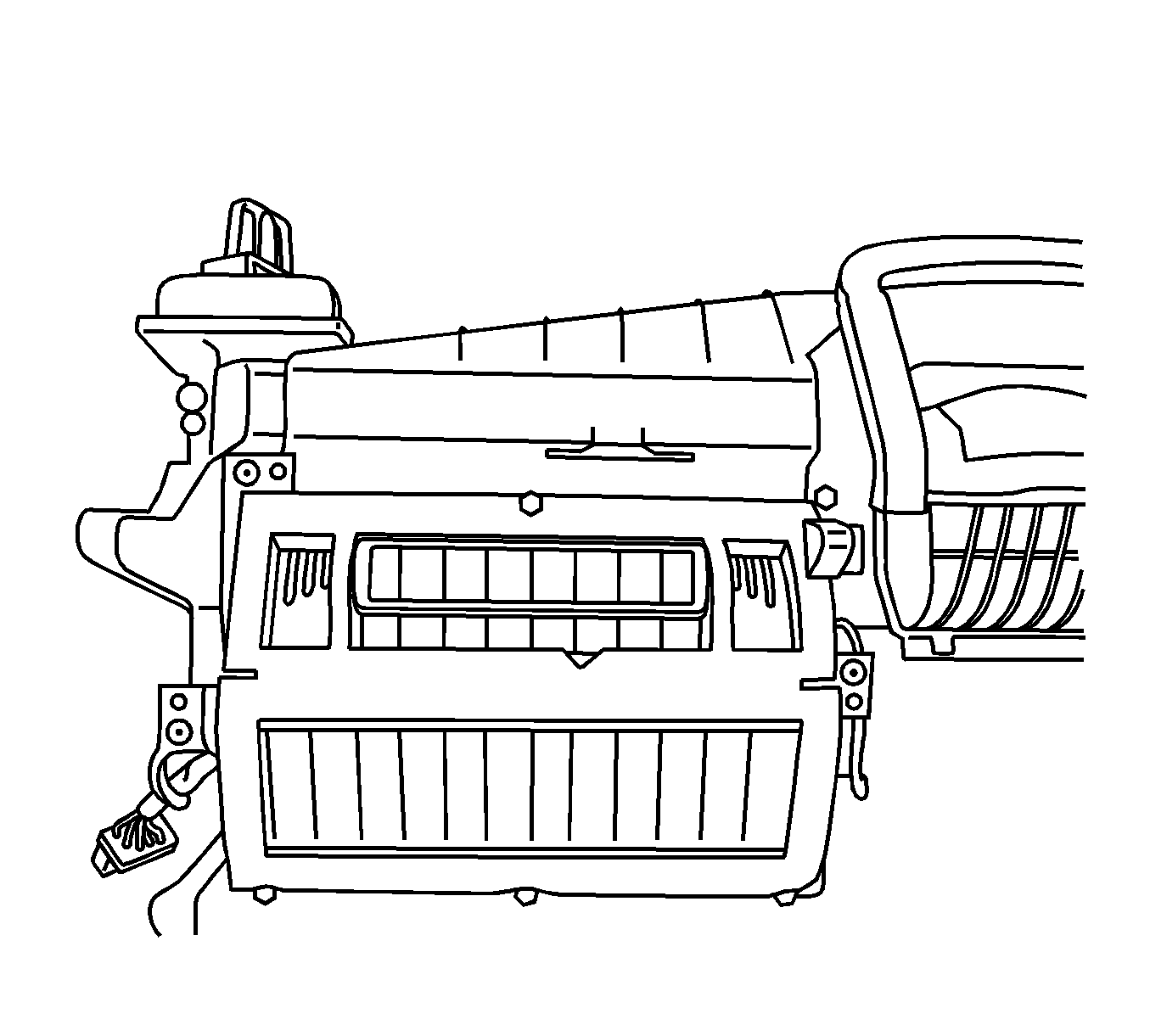
- Remove the 2 rearward retaining screws from the recirculation housing (1).
- Remove the retaining screws from the mode valve assembly.
- Remove the 3 heat stakes from the mode valve assembly using a small chisel.
- Remove the screws from the mode valve actuator.
- Remove the mode valve actuator from the HVAC module assembly.
- Slowly lift the rearward side of the mode valve assembly up and to the left to remove the mode valve assembly.


Important: The right front edge of the mode valve assembly is under the recirculation housing.
Installation Procedure
- From the inside of the mode valve assembly, drill the dimples adjacent to the heat stakes using a 5.5 mm (7/32 in) drill bit.
- Install the right front edge of the mode valve assembly under the recirculation housing.
- Install the mode valve assembly to the HVAC module assembly.
- Install the 2 rearward retaining screws to the recirculation housing (1).
- Install 3 new screws in the locations adjacent to the removed heat stakes in the mode valve assembly.
- Install the screws that were removed from the mode valve assembly to there original position.
- Tighten the recirculation housing, mode valve assembly and heat stake replacement screws.
- Position the mode actuator on to the HVAC module assembly.
- Install the mode valve actuator bolts.
- Install the I/P carrier to the vehicle. Align the I/P carrier to the HVAC module and the hinge pillars.
- Install the bolts to the right and the left I/P carrier.
- Install the bolts to the HVAC module assembly upper support bracket.
- Install the bolts to the HVAC module assembly lower support bracket (1).
- Install the bolts to the HVAC module assembly RH support bracket (2).
- Position the I/P wiring harness to the original position.
- Connect any disconnected ground wires.
- Install the BCM.
- Install the brake pedal brace bolts to the I/P carrier.
- Install the brake pedal and the brake pedal bolt.
- Install the booster push rod to the brake pedal.
- Seat the bottom junction block tabs and snap the top of the junction block to the passenger knee bolster.
- Install the junction block bolt.
- Install the I/P trim pad. Refer to Instrument Panel Trim Pad Replacement .
- Connect the battery negative cable. Refer to Battery Negative Cable Disconnection and Connection .


Notice: Refer to Fastener Notice in the Preface section.
Tighten
Tighten all the screws to 1.5 N·m (13 lb in).
Tighten
Tighten the bolts to 1.5 N·m (13 lb in).
Tighten
Tighten the bolts to 25 N·m (18 lb ft).

Tighten
Tighten the bolts to 4 N·m (36 lb in).

Tighten
Tighten the bolts to 4 N·m (36 lb in).
Tighten
Tighten the bolts to 4 N·m (36 lb in).
Tighten
Tighten the bolts to 10 N·m (89 lb in).
