SERVICE MANUAL UPDATE SEC. 7C NON-SERVICEABLE CLUTCH BEARING

SUBJECT: SMU - SECTION 7C NON-SERVICEABLE CLUTCH RELEASE BEARING (PROCEDURE FOR M27)
VEHICLES AFFECTED: 1991 CHEVROLET, OLDSMOBILE, AND PONTIAC 'W' W/3.4
Models Affected: ---------------- 1991 Chevrolet Lumina Page 7C-9 1991 Pontiac Grand Prix Page 7C-9 1991 Oldsmobile Cutlass Supreme Page 7C-9
A limited number of 1991 vehicles equipped with the 3.4L VIN X (LQ1) and a Manual Transaxle (M27) will be built with a non-serviceable clutch release bearing. You must use the following procedure when removing and installing the transaxle equipped with a non-serviceable clutch release bearing. Vehicles built with a serviceable clutch release bearing should be serviced with procedures listed in the 3.4L V6 Twin Dual Cam Engine Service Manual Supplement (ST503-91 Supp. 3.4L).
Remove or Disconnect
1. Clutch release lever access plug from clutch housing.
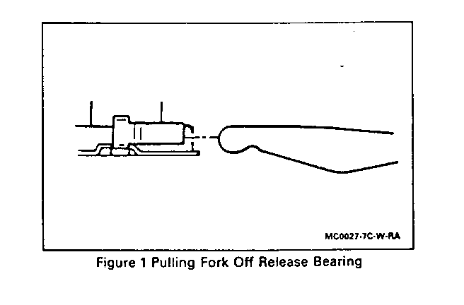
2. Pull the clutch fork lever off the release bearing flanges, as shown in Figure 1. Pull the lever straight out until it stops.
3. Install a wire through the hole in the end of the fork lever. Hold. lever out as far as possible and back towards the transaxle side of the access hole. Wrap one end of the wire around the BOTTOM attaching stud for the actuator.
4. Transaxle from engine. Refer to Manual Transaxle General Information and On-Vehicle Service (Section 7B).
5. Clutch from engine flywheel.
Install Or Connect
1. Clutch to engine flywheel.
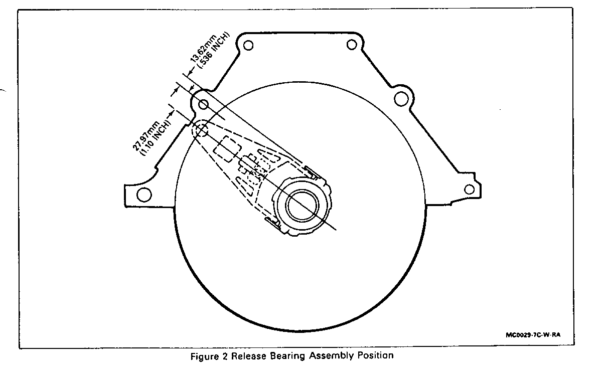
2. Rotate the release bearing to the position shown in Figure 2.
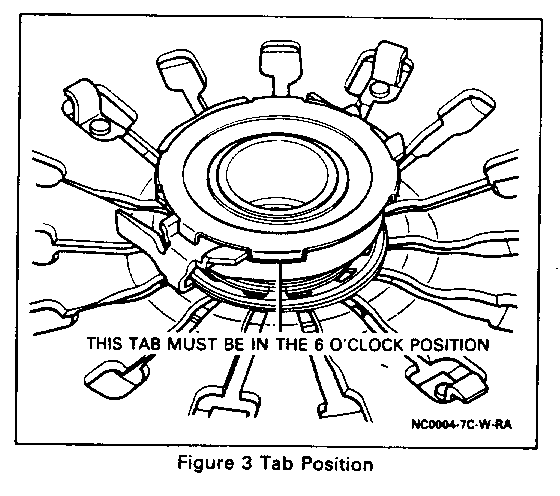
- A folded tab on the release bearing should be in the 6 o'clock position.
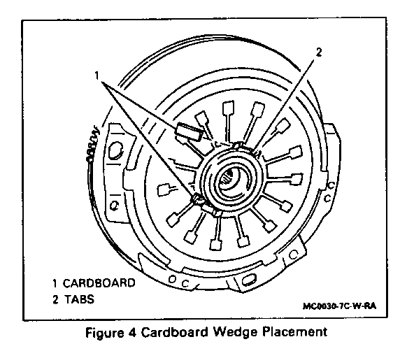
3. Wedge two pieces of cardboard (approximately 1/8" X 1/2" X 1") behind the release bearing to secure it's position. Refer to Figure 4.
IMPORTANT
- Verify the clutch fork lever is wired in correct position to clear the release bearing during the assembly of the transaxle to the engine.
- Do NOT allow the release bearing to rotate during assembly.
- To align splines during installation of transaxle, use locking pliers to rock the output shaft with the transaxle in gear. DO NOT rock the transaxle or turn the crank as this will cause misalignment of the release bearing.
4. Transaxle to engine. Refer to Manual Transaxle General Information and On-Vehicle Service (Section 7B).
A. Transaxle will slide in only until contact with dowels on engine. Remove wire from attaching stud and fork lever and push fork down to engage release bearing, then slide transaxle in completely.
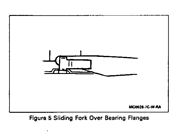
B. Be sure fork is seated properly on release bearing flanges as shown in Figure 5.
C. The cardboard wedge material will exit through the cooling vents in the clutch housing after a few miles of normal driving.
D. Complete transaxle to engine installation. Refer to Manual Transaxle General Information and On-Vehicle Service (Section 7B).
5. Clutch release lever access plug to clutch housing.
Inspect
- Operation of pull clutch by pressing clutch pedal. An unusually hard pedal feel means the fork is out of position.
General Motors bulletins are intended for use by professional technicians, not a "do-it-yourselfer". They are written to inform those technicians of conditions that may occur on some vehicles, or to provide information that could assist in the proper service of a vehicle. Properly trained technicians have the equipment, tools, safety instructions and know-how to do a job properly and safely. If a condition is described, do not assume that the bulletin applies to your vehicle, or that your vehicle will have that condition. See a General Motors dealer servicing your brand of General Motors vehicle for information on whether your vehicle may benefit from the information.
