MANUAL UPDATE-SEC.8A DIAGNOSIS OF SECONDARY COOLANT FAN

VEHICLES AFFECTED: 1989 PONTIAC GRAND PRIX
Please add the following pages to section 8A, additional information for diagnosis of secondary coolant fan, pages 31-8 through 31-16 to your copy of the 1989 Pontiac Grand Prix Service Manual.
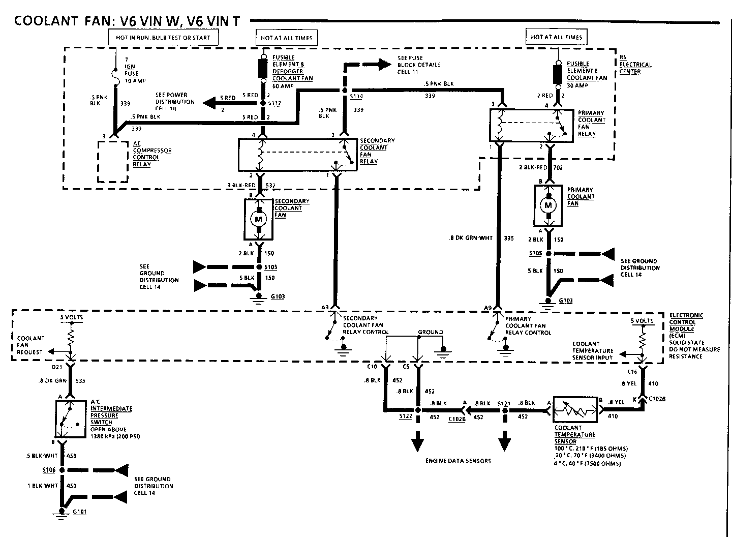
COOLANT FAN
Component Location Page-Fig. --------- --------- --------- A/C Intermediate Pressure....... LH front of engine, near........... 201-4-A Switch (VIN R) transaxle studs A/C Intermediate Pressure...... LH front of engine compartment,.... 201-1-A Switch (VIN W) (VIN T) on accumulator Coolant Fan..................... Engine compartment, behind........ 201-4-A LH side of radiator Coolant Temperature Sensor...... Top LH side of engine, below....... 201-5-A (VIN R) coolant outlet Coolant Temperature Sensor...... Top LH rear of engine, below (VIN W) (VIN T) coolant outlet Electronic Control Module....... Engine compartment, front of....... 201-8-C (ECM) RH strut tower Primary Coolant Fan............. Engine compartment, behind LH...... 201-8-C side of radiator RS Electrical Center............ Engine compartment, front of....... 201-8-C RH strut tower Secondary Coolant Fan........... Engine compartment, behind RH side of radiator C102B (10 cavities)............. RH front of engine compartment,.... 201-8-C below RS Electrical Center G101 (VIN R).................... Lower front of engine, near........ 201-5-D starter G101 (VIN W)(VIN F)............. Rear of engine, below exhaust...... 201-4-C manifold G102 (VIN R).................... RH side of engine.................. 201-3-A G102 (VIN W).................... Rear of engine, below exhaust...... 201-4-C manifold G103 (VIN R).................... LH front of engine, on transaxle... 201-4-A stud G103 (VIN W)(VIN T)............. On engine stud, front of transaxle. 201-1-A assembly S104............................ Engine harness, RH rear of engine.. 201-3-A S105............................ Engine harness, bottom center of... 201-0-A radiator support S106............................ Engine harness, RH front of engine.. 201-0-A compartment S114............................ Engine harness, below RS Electrical. 201-0-A Center S121............................ Engine harness, top LH rear of engine S122............................ Engine harness, near RH frame....... 201-0-A rail S128............................ Engine harness, bottom RH rear of... 201-4-C engine
TROUBLESHOOTING HINTS
Try the following checks before doing the System Diagnosis.
1. If both Coolant Fans do not operate, check IGN Fuse.
2. If a Coolant Fan does not operate, check Fusible Links E and G.
3. If a Coolant Fan runs with the Ignition Switch in OFF, replace the suspect Coolant Fan Relay.
Go to System Diagnosis for diagnostic tests.
SYSTEM DIAGNOSIS
Diagnostic steps for the symptoms listed in the following table are listed after the table.
If any diagnositc codes are present refer to Section 6E3.
SYMPTOM TABLE
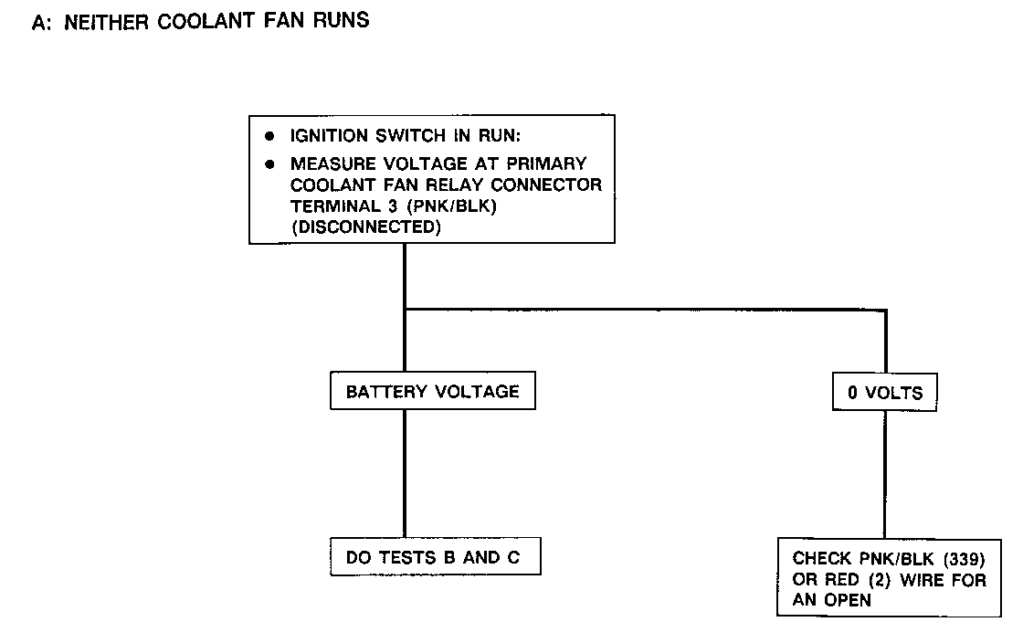
A: Neither Coolant Fan Runs
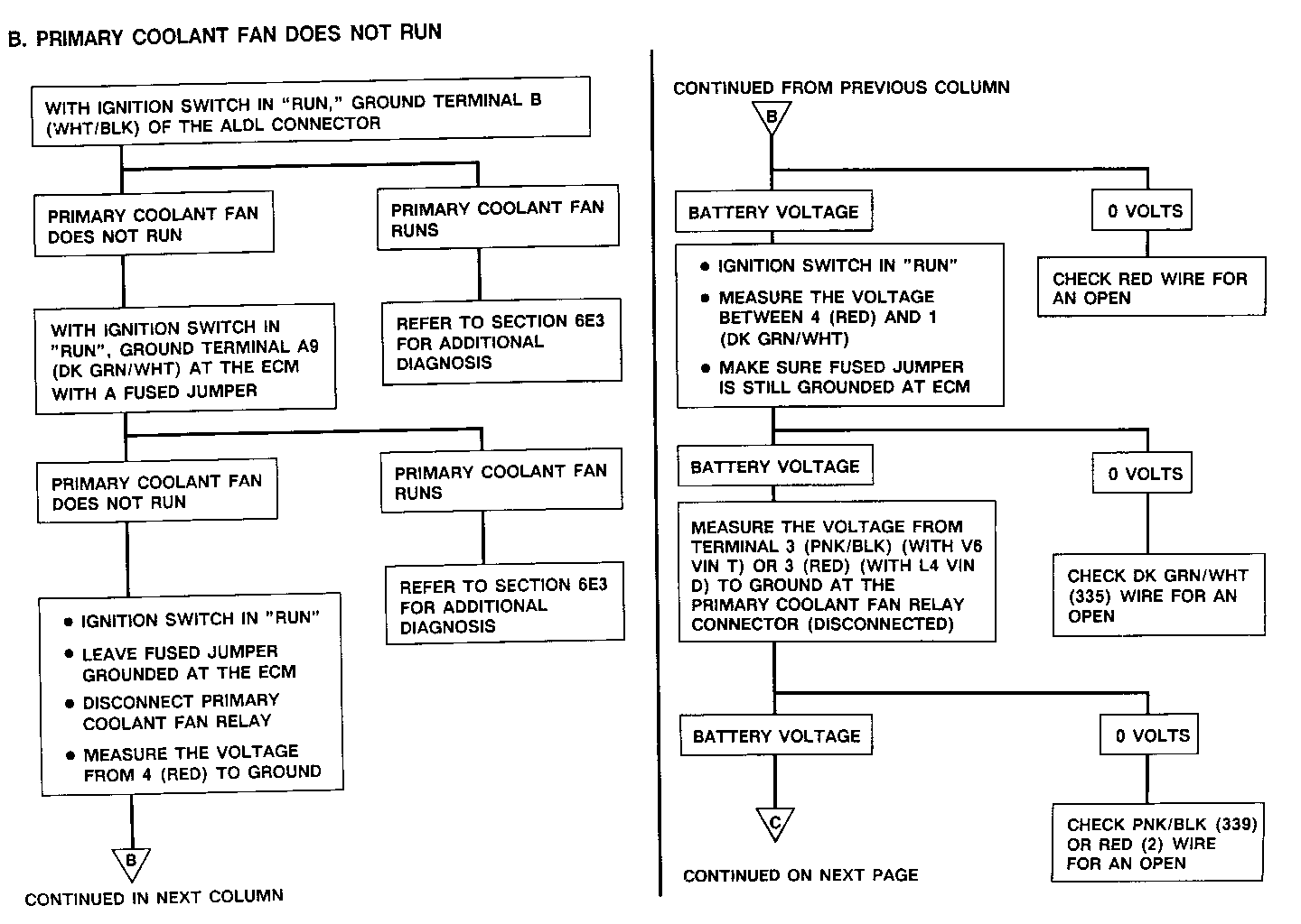
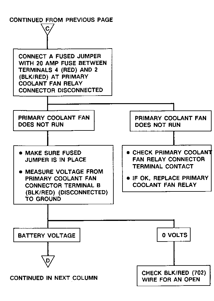
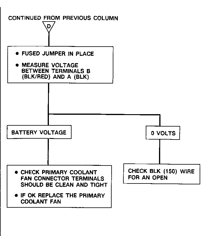
B: Primary Coolant Fan does not run
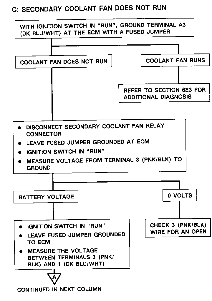
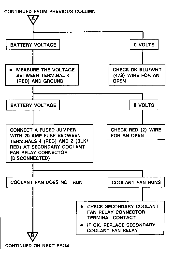
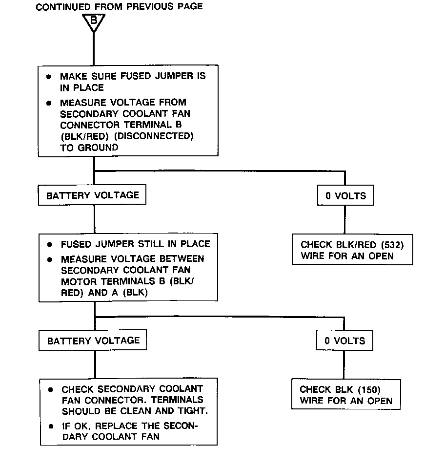
C: Secondary Coolant Fan does not run
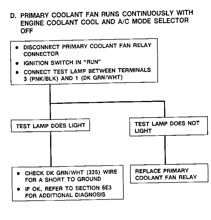
D: Primary Coolant Fan runs continuously with engine coolant cool and A/C mode selector off
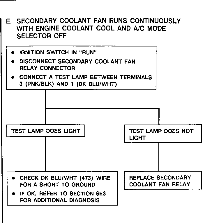
E: Secondary Coolant Fan runs continuously with Engine coolant cool and A/C mode selector off
Circuit Operation
Each Coolant Fan is turned on and off by a separate Coolant Fan Relay.
The Primary Coolant Fan Relay coil is grounded through the ECM when vehicle speed is less than a speed determined by the ECM and the engine coolant reaches 108 DEG C (227 DEG F) with A/C off, and 106 DEG C (223 DEG F) with A/C on. The contacts close and voltage is applied through the Primary Coolant Fan. The Primary Coolant Fan runs until the Ignition Switch is turned off, or coolant temperature decreases to 104 DEG C (220 DEG F) with A/C off or 102 DEG C (216 DEG F) with A/C on.
The Secondary Coolant Fan Relay coil is grounded through the ECM when the coolant temperature reaches 118 DEG C (245 DEG F). The contacts close and voltage is applied to the Coolant Fan. The fan then runs at high speed. The Coolant Fan will continue to run at high speed with the Ignition Switch in RUN until the coolant temperature lowers to 114 DEG C (238 DEG F).
General Motors bulletins are intended for use by professional technicians, not a "do-it-yourselfer". They are written to inform those technicians of conditions that may occur on some vehicles, or to provide information that could assist in the proper service of a vehicle. Properly trained technicians have the equipment, tools, safety instructions and know-how to do a job properly and safely. If a condition is described, do not assume that the bulletin applies to your vehicle, or that your vehicle will have that condition. See a General Motors dealer servicing your brand of General Motors vehicle for information on whether your vehicle may benefit from the information.
