For 1990-2009 cars only
Tools Required
| • | J 45059 Angle Meter |
| • | KM-618-A Insulator Installer |
| • | CH-46839 Crossmember Centering Tool |
Removal Procedure
- Raise and support the rear of the vehicle. Refer to Lifting and Jacking the Vehicle in General Information.
- Remove the rear wheels and tires. Refer to Tire and Wheel Removal and Installation in Tires and Wheels.
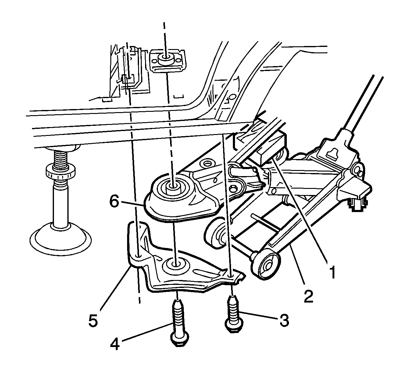
- Position a floor jack (2) with a suitable block of wood (1) mounted on top of the jacks' lifting pad to support and protect the rear suspension crossmember assembly (6) during the procedure.
- Take up the weight of the crossmember by raising the floor jack to make contact with the crossmember, nearest to the side on which the bushing is to be replaced.
- Remove the brace (5) and the crossmember to vehicle underbody attaching bolts (3), (4) from the same side of the vehicle.
- Lower the floor jack slightly to allow clearance between the crossmember and the vehicle underbody.
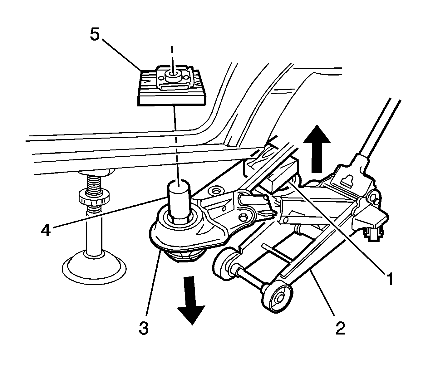
- Place a suitable block of wood (5), approximately 50 mm in width by 50 mm in length by 25 mm in depth, along with a suitable metal distance piece (4), approximately 50 mm in length by 30 mm in diameter, between the bushing to be removed and the underbody.
- Raise the floor jack (2) slowly with a suitable block of wood (1) mounted on top, allowing the clearance to reduce between the crossmember (3) bushing, distance piece and the underbody to apply force in a downward direction on the bushing.
- Increase pressure applied by the floor jack, gradually pressing the bushing downward and free of the crossmember. The vehicle weight and the up-ward movement of the jack will apply adequate force in a downward direction to facilitate removal of the bushing.
- Remove and discard the bushing together with the crossmember front mounting to underbody bolt.
- Lower the Floor Jack to allow clearance for the installation of the new bushing.
Installation Procedure
- Apply a small amount of petroleum jelly to the outer diameter area of the new bushing, to assist the installation of the bushing into the crossmember bushing aperture.
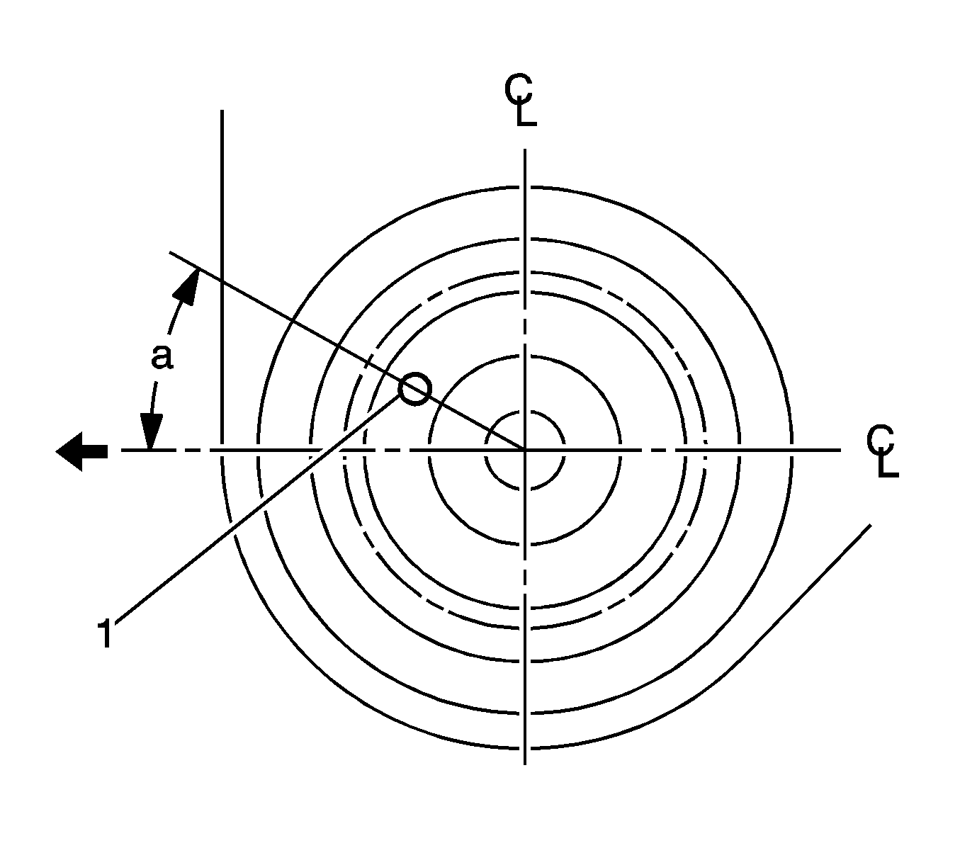
- Position the blue identification mark (1) toward the front of the vehicle and 30° (a) toward the centerline of the vehicle. Apply pressure to start the leading edge of the bushing into it's aperture.
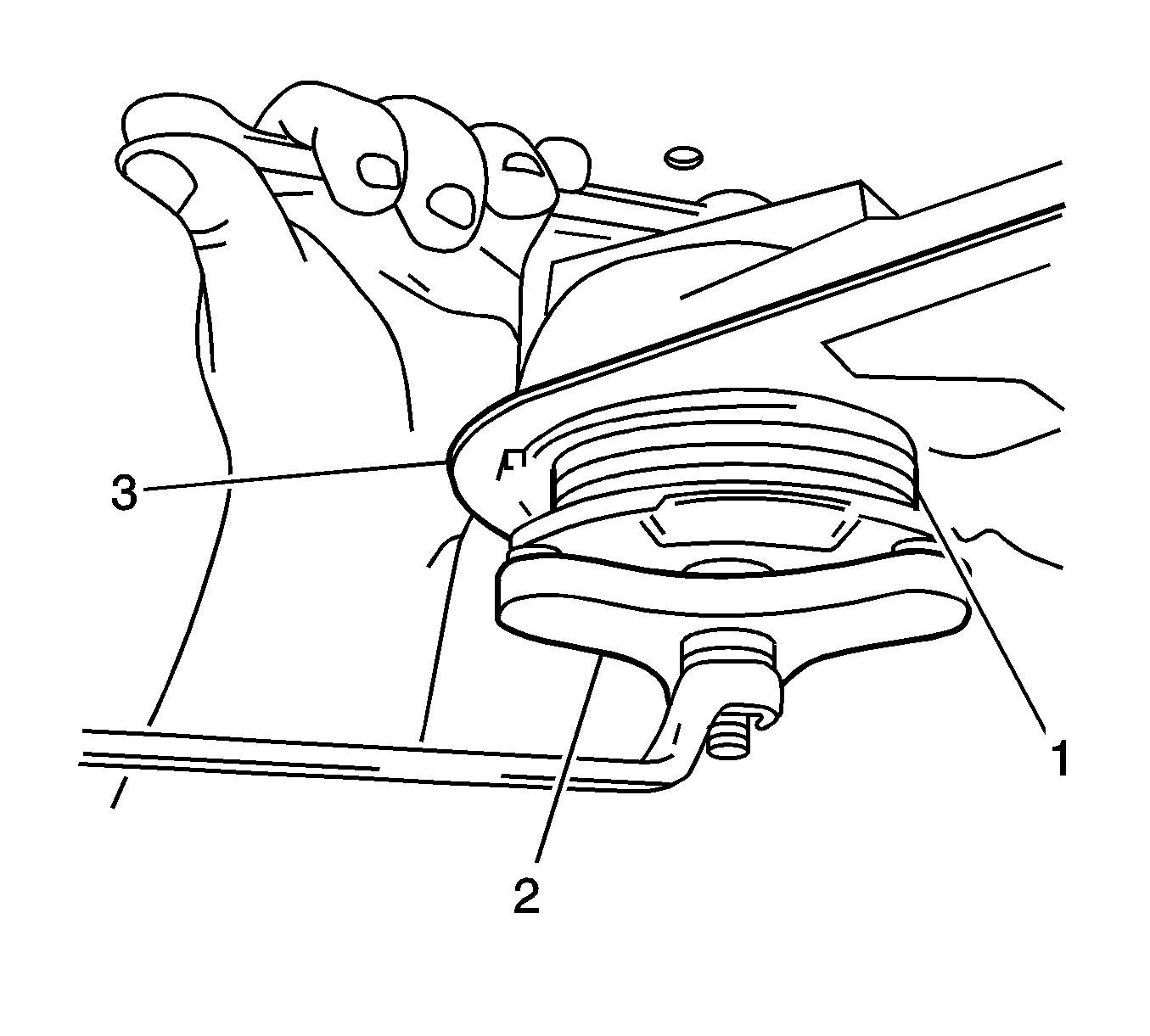
- Offer the new bushing (1) up to the crossmember (3).
- Apply the KM-618-A (2) to the bushing (1) and crossmember (3).
- Draw the remaining exposed section of the new bushing (1) into the crossmember (3), using the KM-618-A (2).
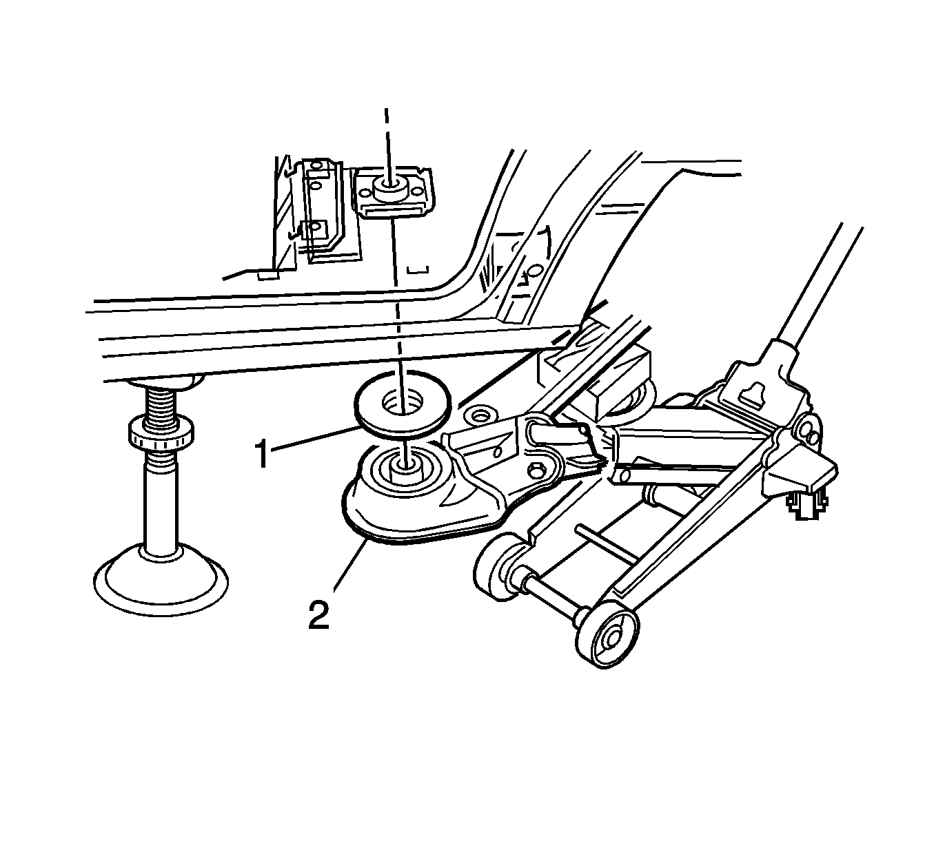
- Position the upper insulator pad (1), between the underbody and the upper part of the bushing and crossmember (2).
- With the floor jack still in position to support and protect the rear suspension crossmember assembly, raise the crossmember using the floor jack.
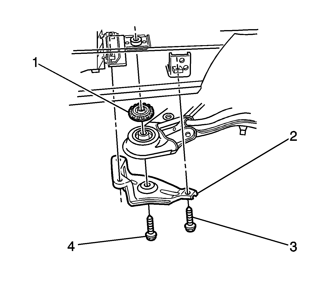
- Install the brace (5), a new crossmember mounting to underbody bolt (4), and the three small original brace attaching bolts (3).
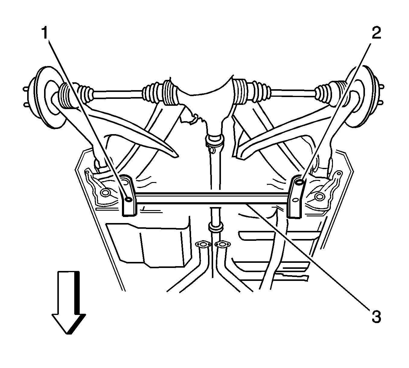
- Fit the CH-46839 to the underbody.
- The rear crossmember centering tool (3) locates into 19 mm (0.74 in) diameter body datum holes (1) positioned forward of the rear suspension support.
- With the aid of an assistant, position the rear suspension support until the location pins (2) of the rear crossmember centering tool (3) engage the alignment holes on the rear suspension support assembly.
- Locate the brace to underbody bolts (4).
- Tighten the brace to underbody bolts to 125 N·m (92 lb ft).
- Use the J 45059 in order to tighten the bolts an additional 40 degrees.
- Locate the bolts (3) attaching the rear suspension support insulator bracket (2) to the vehicle.
- Remove the CH-46839 .
- Lower the jack and remove from under the vehicle.
- Install the rear wheels and tires. Refer to Tire and Wheel Removal and Installation in Tires and Wheels.
- Remove the safety stands and lower the vehicle.
- With the vehicle at curb weight, bounce the rear of the vehicle several times to settle the suspension.

Important: Do not tighten the bolts at this stage.
Tighten

Tighten
Tighten the rear suspension support insulator bracket bolts (3) to 70 N·m (52 lb ft).
