For 1990-2009 cars only
Tools Required
| • | J 45059 Angle Meter |
| • | CH-46839 Rear Crossmember Centering Tool |
Removal Procedure
- Raise and support the vehicle. Refer to Lifting and Jacking the Vehicle in General Information.
- Remove the rear tire and wheel assemblies. Refer to Tire and Wheel Removal and Installation in Tires and Wheels.
- Remove the 2 mufflers. Refer to Muffler Replacement in Engine Exhaust.
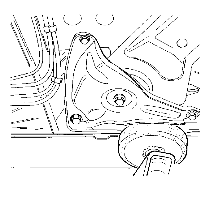
- Loosen the 6 bolts that retain the 2 rear suspension support braces to the body.
- Loosen the 2 bolts that retain the rear suspension support to the body.
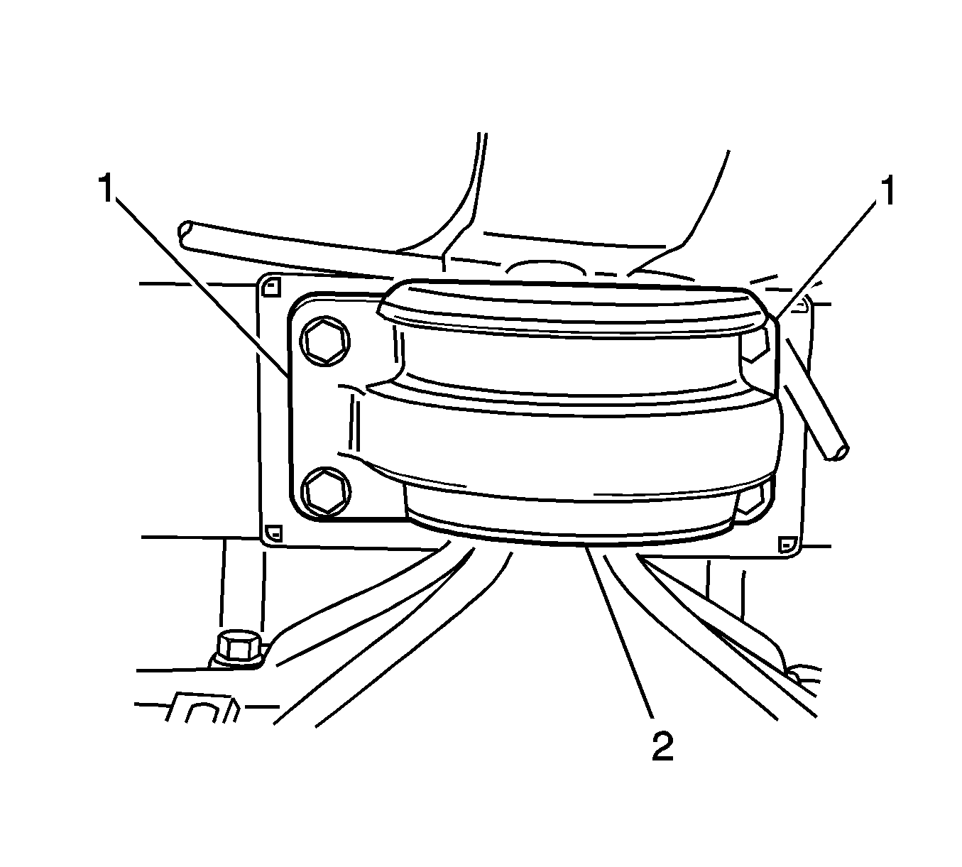
- Use paint or a scribe in order to mark the outline (1) of the differential carrier assembly mount (2) on the body.
- Use a jack in order to support the mount.
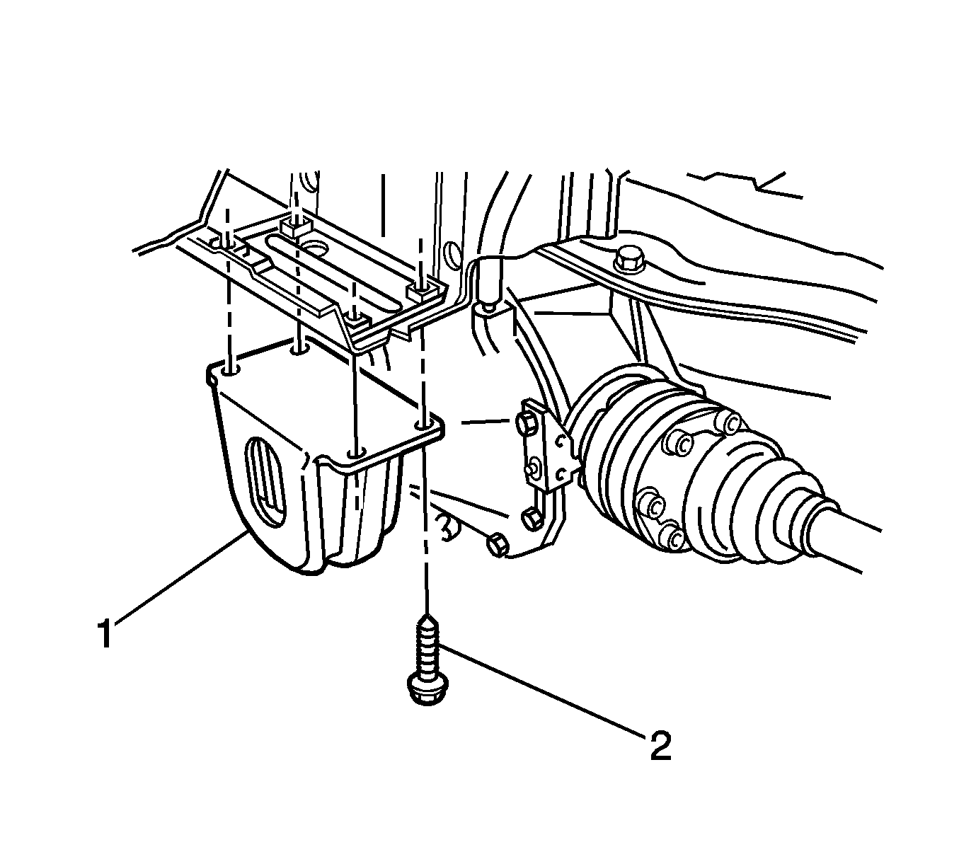
- Remove and discard the 4 bolts (2) that retain the mount (1) to the body.
- Lower the mount and the rear suspension support in order to access the bolts that retain the stabilizer shaft insulator brackets to the rear suspension support.
- Remove the bolt that retains the stabilizer shaft insulator bracket to the rear suspension support.
- Use a flat-bladed tool as a lever in order to remove the bracket from the rear suspension support.
- Remove the bracket from the insulator.
- Remove the insulator from the shaft.

Important: Position the lift pads in order to minimize interference with the rear suspension support and the braces.


Important: Do not allow the propeller shaft or the wheel drive shafts to touch the exhaust system.

Installation Procedure
- Install the insulator to the stabilizer shaft.
- Install the stabilizer shaft insulator bracket to the insulator.
- Install the bracket to the slot on the rear suspension support.
- Install the bolt to the bracket.
- Raise the jack with the differential carrier assembly mount (1) and the rear suspension support.
- Align the mount with the match marks.
- Install 4 NEW bolts (2) in order to retain the mount to the body.
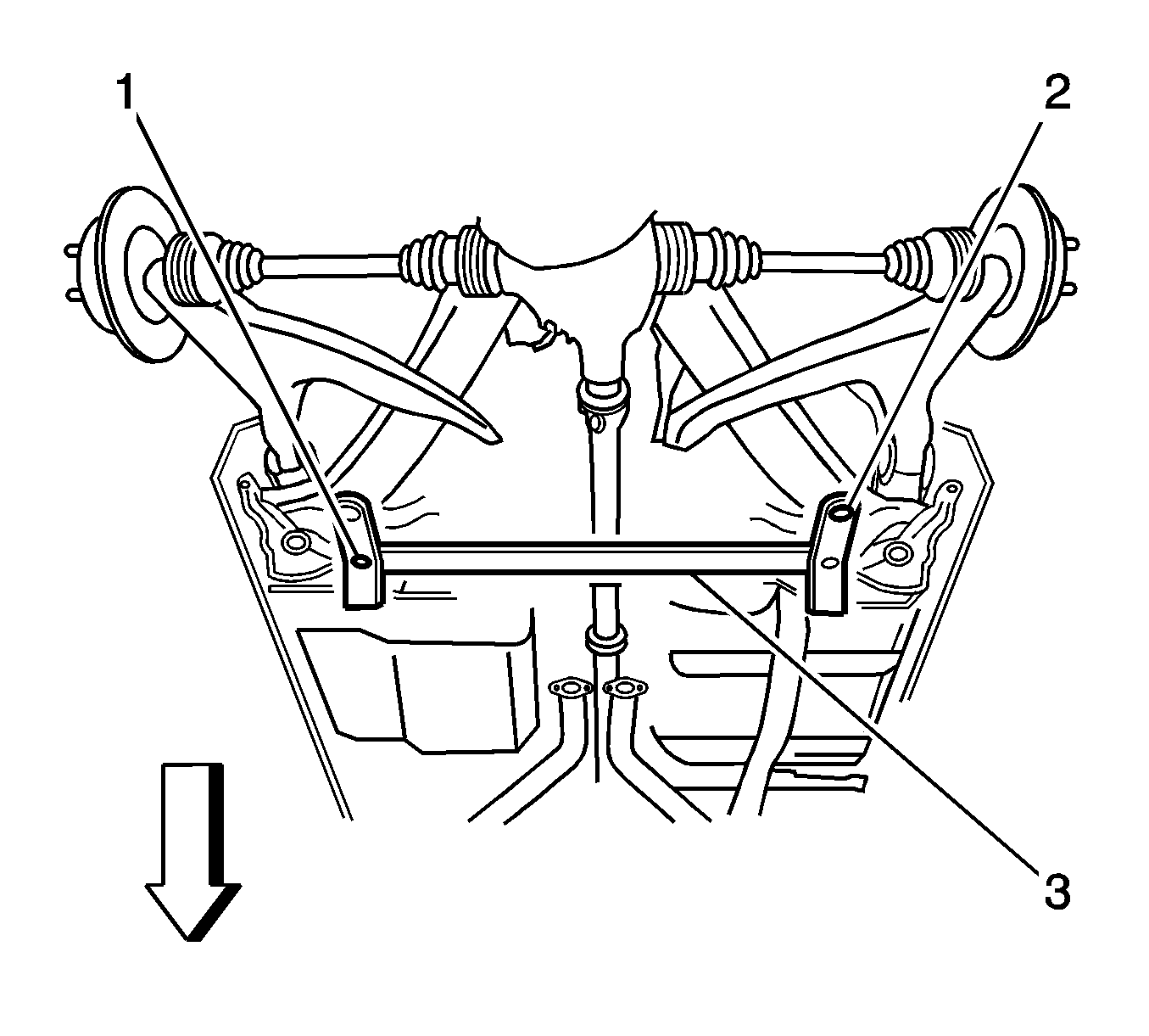
- Fit the CH-46839 to the underbody.
- With the aid of an assistant, position the rear suspension support.
- Tighten the 2 bolts that retain the rear suspension support to the body.
- Tighten the bolts to 125 N·m (92 lb ft).
- Use the J 45059 in order to tighten the bolts an additional 40 degrees.
- Tighten the 4 bolts that retain the differential mount to the body.
- Tighten the bolts to 35 N·m (26 lb ft).
- Use the J 45059 in order to tighten the bolts an additional 60 degrees.
- Tighten the 6 bolts that retain the 2 rear suspension support braces to the body.
- Remove the CH-46839 from the vehicle.
- Remove the jack from the vehicle.
- Install the 2 mufflers. Refer to Muffler Replacement in Engine Exhaust.
- Install the rear tire and wheel assemblies. Refer to Tire and Wheel Removal and Installation in Tires and Wheels.
- Lower the vehicle.

Notice: Refer to Fastener Notice in the Preface section.
Tighten
Tighten the bolt to 22 N·m (16 lb ft).

Important: Do not tighten the bolts yet.

The CH-46839 locates into 19 mm (0.74 in) diameter body datum holes (1) positioned forward of the rear suspension support.
The locating pins (2) of the CH-46839 engage the alignment holes in the rear suspension support.
Tighten
Tighten
Tighten
Tighten the bolts to 70 N·m (52 lb ft).
