For 1990-2009 cars only
Removal Procedure
- Raise and support the vehicle. Refer to Lifting and Jacking the Vehicle in General Information.
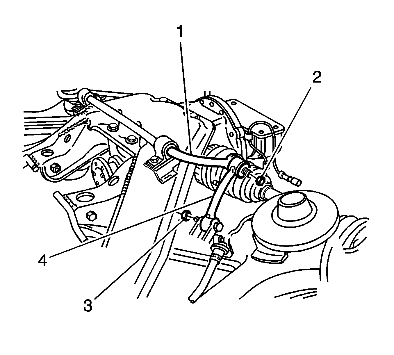
- Remove the nut (3) that retains the stabilizer shaft link (4) to the rear suspension lower control arm.
- Remove bolt that retains the link to the control arm.
- Remove the link from the control arm.
- Remove the nut (2) that retains the link to the stabilizer shaft (1).
- Remove the bolt that retains the link to the stabilizer shaft.
- Remove the link from the stabilizer shaft.

Installation Procedure
- Clean the stabilizer shaft (1) and the link (4) mating surfaces in order to protect the bushings from damage.
- Install the link to the stabilizer shaft.
- Install the nut (2) and the bolt in order to retain the link to the stabilizer shaft.
- Install the link to the rear suspension lower control arm.
- Install the nut (3) and the bolt in order to retain the link to the control arm.
- Lower the vehicle.
- With the weight of the vehicle on the tire and wheel assemblies, bounce the rear of the vehicle several times in order to stabilize the rear suspension.
- Tighten the link nuts and the bolts.

Important: Do not tighten the nuts or the bolts yet. The weight of the vehicle must be on the tire and wheel assemblies before tightening the suspension fasteners.
Notice: Refer to Fastener Notice in the Preface section.
Tighten
Tighten the nuts and the bolts to 98 N·m (72 lb ft).
