For 1990-2009 cars only
Tools Required
| • | J 42188 Ball Joint Separator |
| • | J 45059 Angle Meter |
Removal Procedure
- Raise and support the vehicle on an alignment rack. Refer to Lifting and Jacking the Vehicle .
- Remove the tire and wheel assembly. Refer to Tire and Wheel Removal and Installation .
- Remove the front brake rotor. Refer to Front Brake Rotor Replacement .
- Remove the cotter pin from the outer tie rod nut.
- Remove the outer tie rod nut.
- Use the OTC 7314A, or the equivalent ball joint separator, in order to separate the outer tie rod from the knuckle.
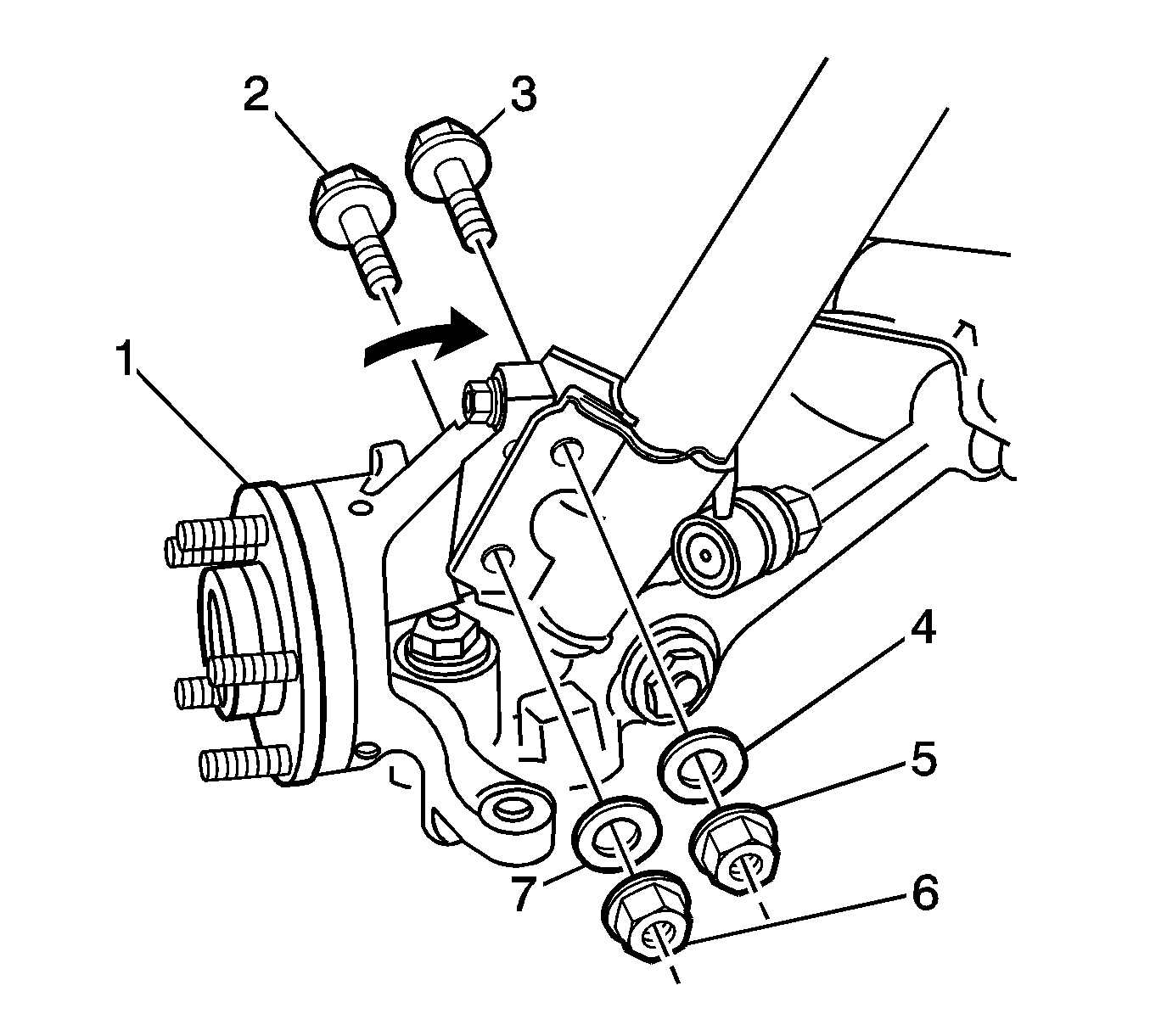
- Remove and discard the 2 nuts (5, 6).
- If equipped, remove the 2 washers (4, 7) from the bolts.
- Remove and discard the 2 bolts (2, 3).
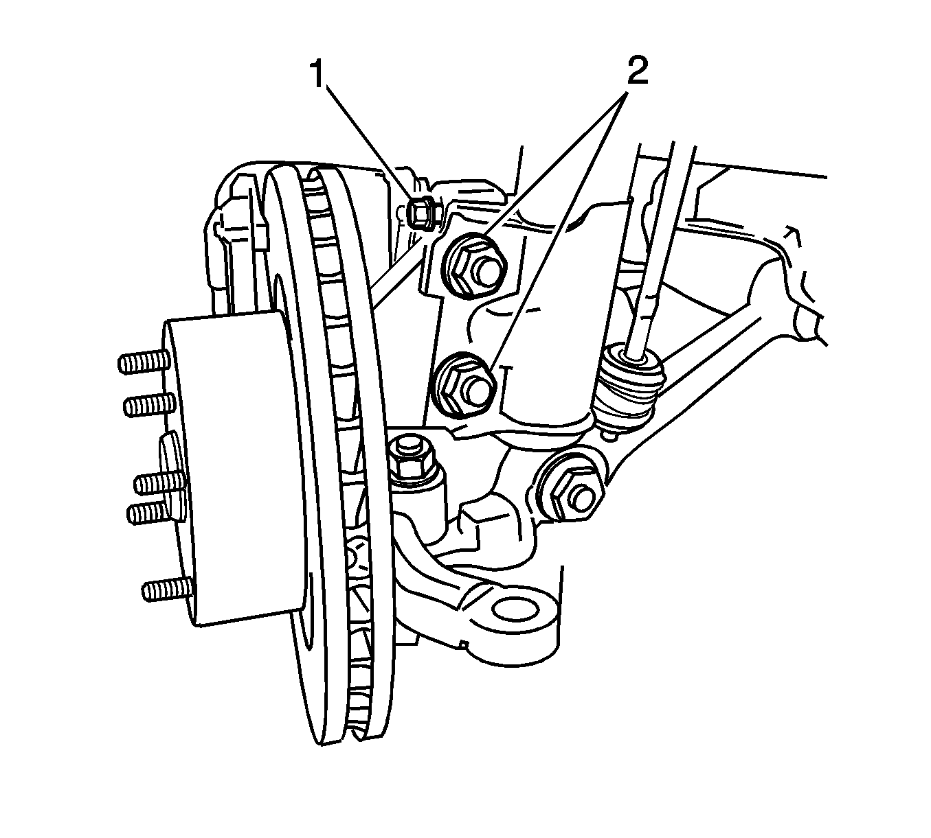
- If you are replacing the knuckle, remove the camber adjusting screw from the knuckle.
- Separate the steering knuckle from the strut.
- Remove and discard the nut that retains the control arm ball joint stud to the knuckle.
- Use the J 42188 , or equivalent, in order to separate the control arm ball joint stud from the knuckle.
- Remove the wheel bearing and hub assembly (1). Refer to Front Wheel Bearing and Hub Replacement .
- Remove the knuckle from the vehicle.

Important: The camber adjustment screw has thread sealant in the form of micro-encapsulation.
Installation Procedure
- Install the wheel bearing and hub assembly (1). Refer to Front Wheel Bearing and Hub Replacement .
- Install the steering knuckle to the control arm ball joint stud.
- Align the bolt holes in the knuckle with the bolt holes in the strut.
- Install the 2 NEW bolts (2, 3) in order to retain the knuckle to the strut.
- Install the 2 washers (4, 7) to the bolts.
- Install the 2 NEW nuts (5, 6) to the bolts.
- Position a jack and a block of wood below the control arm ball joint.
- Raise the jack in order to support the control arm.
- Raise the jack in order to seat the knuckle on the control arm ball joint stud.
- Install the nut to the control arm ball joint stud.
- Remove the jack and the wood.
- Ensure the plastic spacer is on the ball stud for the outer tie rod end.
- Install the outer tie rod to the knuckle.
- Install the nut to the ball stud for the outer tie rod.
- Install the cotter pin into the hole in the tie rod stud.
- If you removed the camber adjusting screw (1), install the camber adjusting screw to the knuckle.
- Tighten the 2 nuts (2) that retain the strut to the knuckle.
- Install the front brake rotor. Refer to Front Brake Rotor Replacement .
- If you replaced the hub, measure the assembled lateral runout (LRO) of the brake rotor in order to ensure optimum performance of the disc brakes. Refer to Brake Rotor Assembled Lateral Runout Measurement .
- If the brake rotor assembled LRO measurement exceeds the specification, adjust the LRO to the specification. Refer to Brake Rotor Assembled Lateral Runout Correction .
- Install the tire and wheel assembly. Refer to Tire and Wheel Removal and Installation .
- Lower the vehicle onto the alignment rack in order to place the weight of the vehicle onto the tires.
- Push down on the front bumper 3 times in order to stabilize the suspension.
- Measure the wheel alignment. Refer to Wheel Alignment Measurement .
- If necessary, adjust the alignment to the specification. Refer to Wheel Alignment Specifications .
- Tighten the 2 nuts that retain the strut to the knuckle.
- Tighten the nuts to 100 N·m (74 lb ft).
- Use the J 45059 in order to tighten the nuts an additional 90 degrees.
- Lower the vehicle.

Important: Do NOT tighten the bolts or the nuts yet.
Notice: Refer to Fastener Notice in the Preface section.
Tighten
Tighten the nut to 60 N·m (44 lb ft).
Important: Do not loosen the nut in order to insert the cotter pin.
Tighten
Tighten the nut to 68 N·m (50 lb ft).
Align the cotter pin slot by tightening the nut up to 1/6 additional turn,
or 85 N·m (63 lb ft) maximum.

Tighten
Tighten the nuts to 85 N·m (63 lb ft).
If necessary, rotate the camber adjusting screw in order to adjust the front camber.
Tighten
