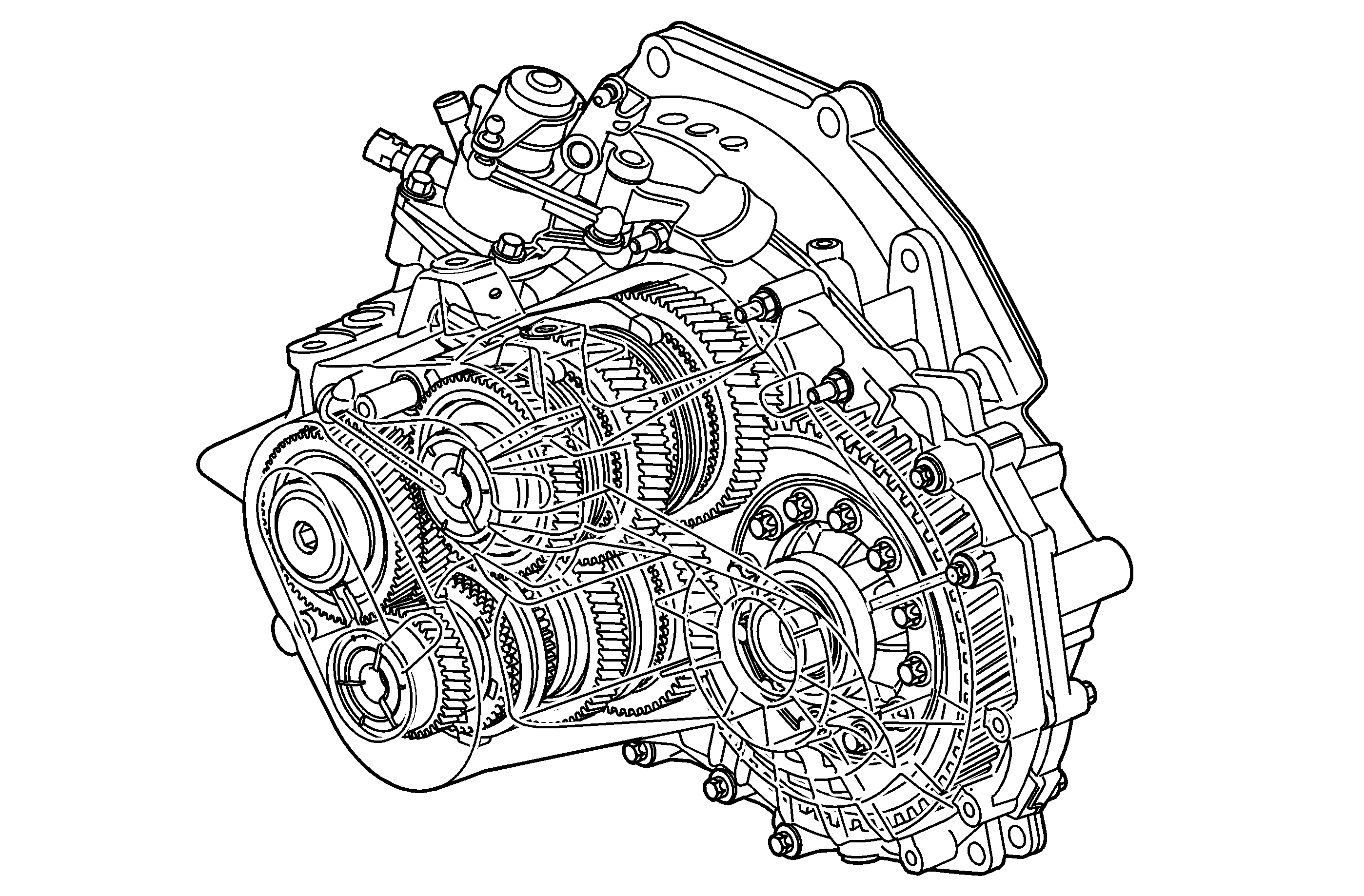
The manual 6 speed gearbox has synchronizers on all gears, including reverse. To improve synchronization, the hub for 1st/2nd has three cones. 3rd/4th and reverse has a double cone, and 5th/6th has a single cone.
The gearbox has two output shafts. The lower shaft transfers power for 1st, 2nd, 5th, 6th and reverse gears. The upper output shaft transfers power for 3rd, 4th and reverse gears. This means that both intermediate shafts have a pinion gear that is constantly meshed with the crown wheel.
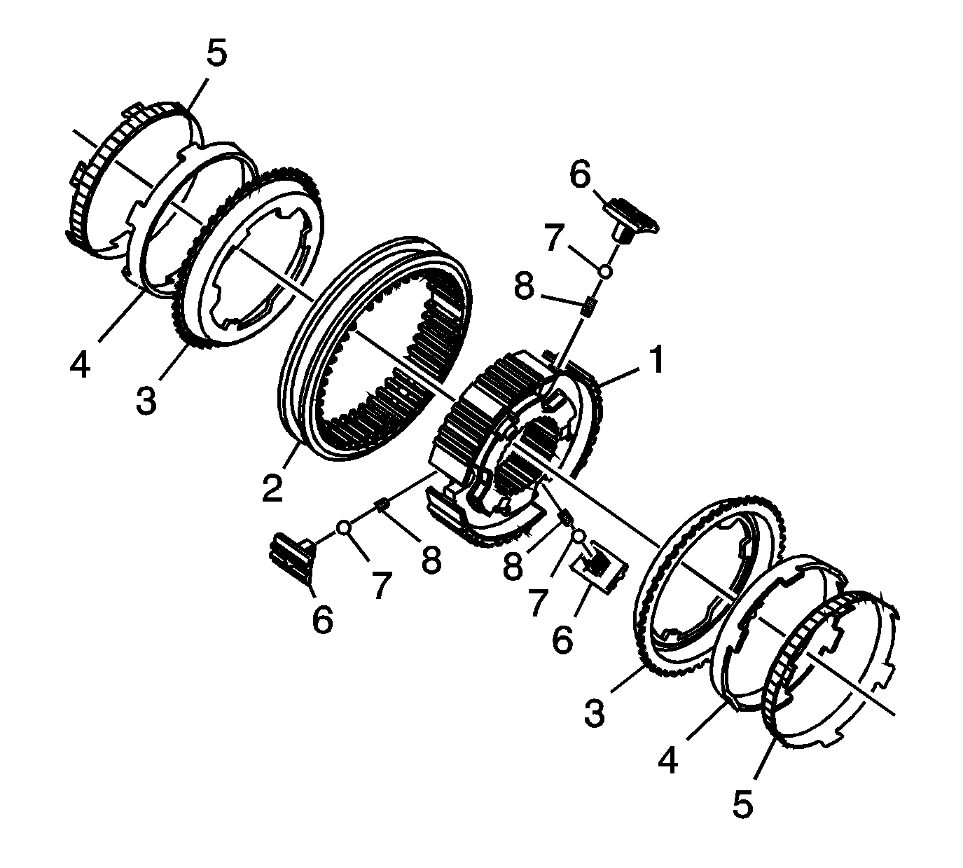
The components of the synchronizer are as follows:
| • | Hub (1) |
| • | Synchronizer sleeve (2) |
| • | Outer synchronizer cone (3) |
| • | Intermediate synchronizer cone (4) |
| • | Inner synchronizer cone (5) |
| • | Insert (6) |
| • | Ball (7) |
| • | Spring (8) |
If 1st or 2nd gear is engaged, the sleeve pulls the inserts slightly, which then start to bear against the outer baulk ring. This produces a pre-synchronization that is advantageous for the continued synchronization/shifting. In this position, the ball is pressed down against the sleeve. The ball does not reach a new recess in the sleeve. Instead, the forces required to keep the gear engaged primarily come from segments in the gear selector mechanism. This function can be found in all synchronizer hubs.
When counting the synchronizer cones, start from the shaft.
The design of the gear box, with double intermediate shafts, means that the gear box is short, compact and very torsionally stiff. The gear box is designed to be able to continuously transfer 400 N·m (295 lb ft) of torque.
Note that the gears on the input shaft are called pinions, driving gears. The gears on the output shaft are called gear wheels, driven gears.
The input and output shafts and differential have been mounted with taper roller bearings to achieve maximum rigidity of the shafts under load. Shims must only be added to the bearings/shafts under the outer ring in the gear case, not in the clutch housing. Shims are available in thicknesses of 0.8-2.3 mm (0.03-0.09 in) in 0.05 mm (0.002 in) intervals. The power from the engine is transferred directly to the input shaft. The way in which the gear box works is shown by the illustration.
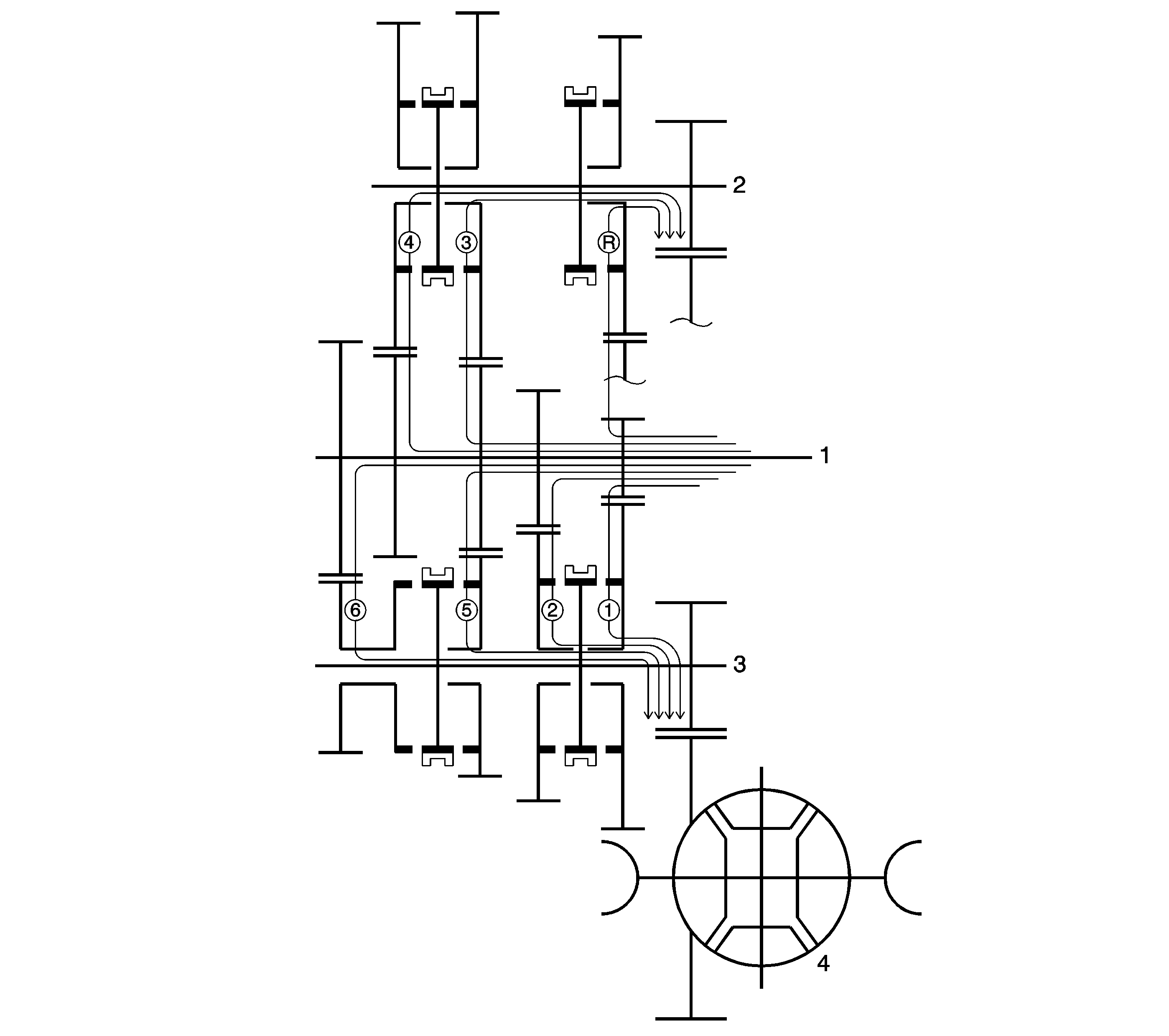
The input shaft (1), upper output shaft (2), lower output shaft (3) and differential (4) are shown in the illustration.
Power Flow
1st Gear
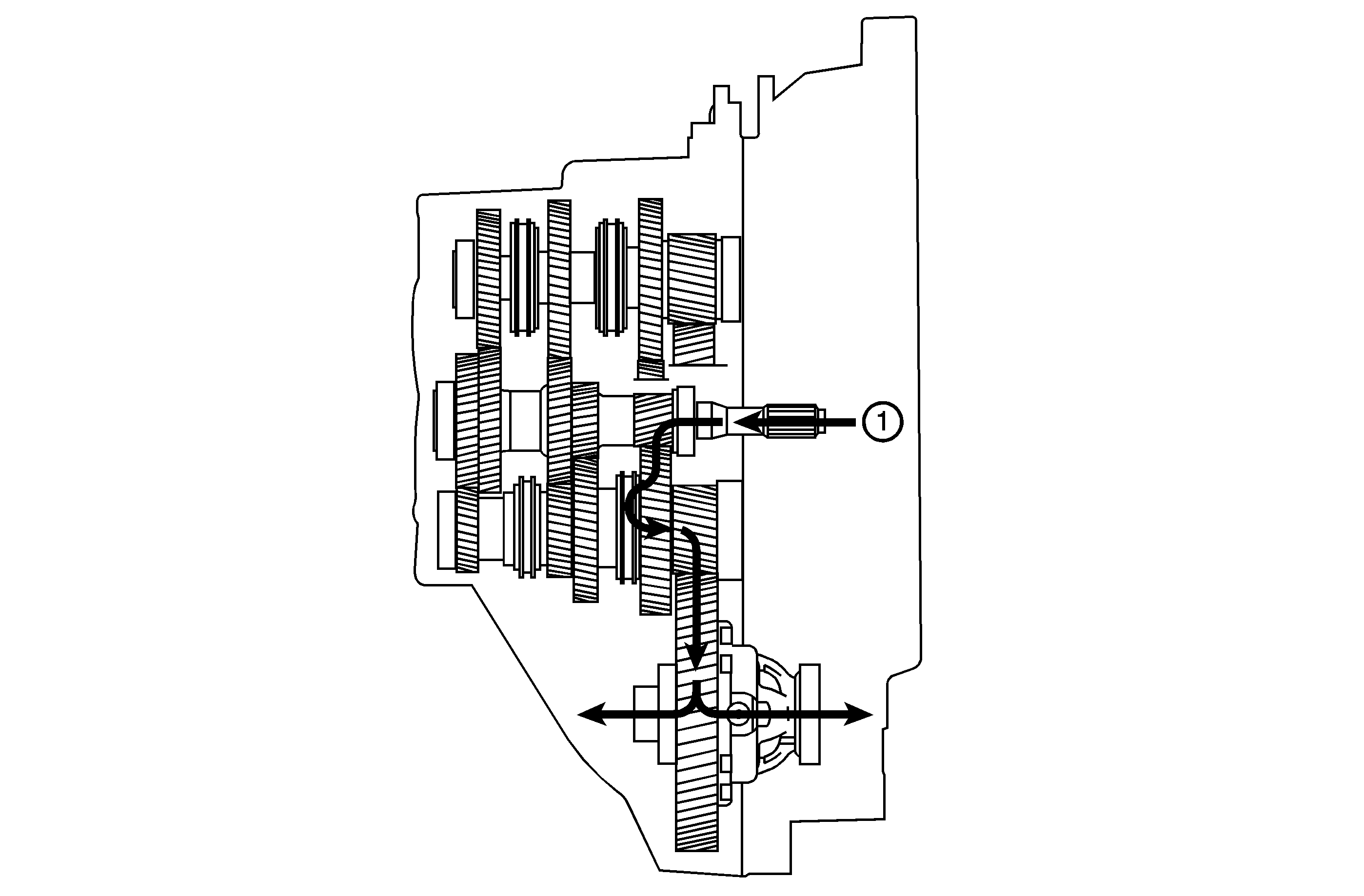
In 1st gear range, power is transmitted via the 1st gear pinion, fixed on the output shaft, to output shaft 1. 1st gear wheel is locked to the output shaft 1, on which it is journalled, by the 1st/2nd synchronizer sleeve.
2nd Gear
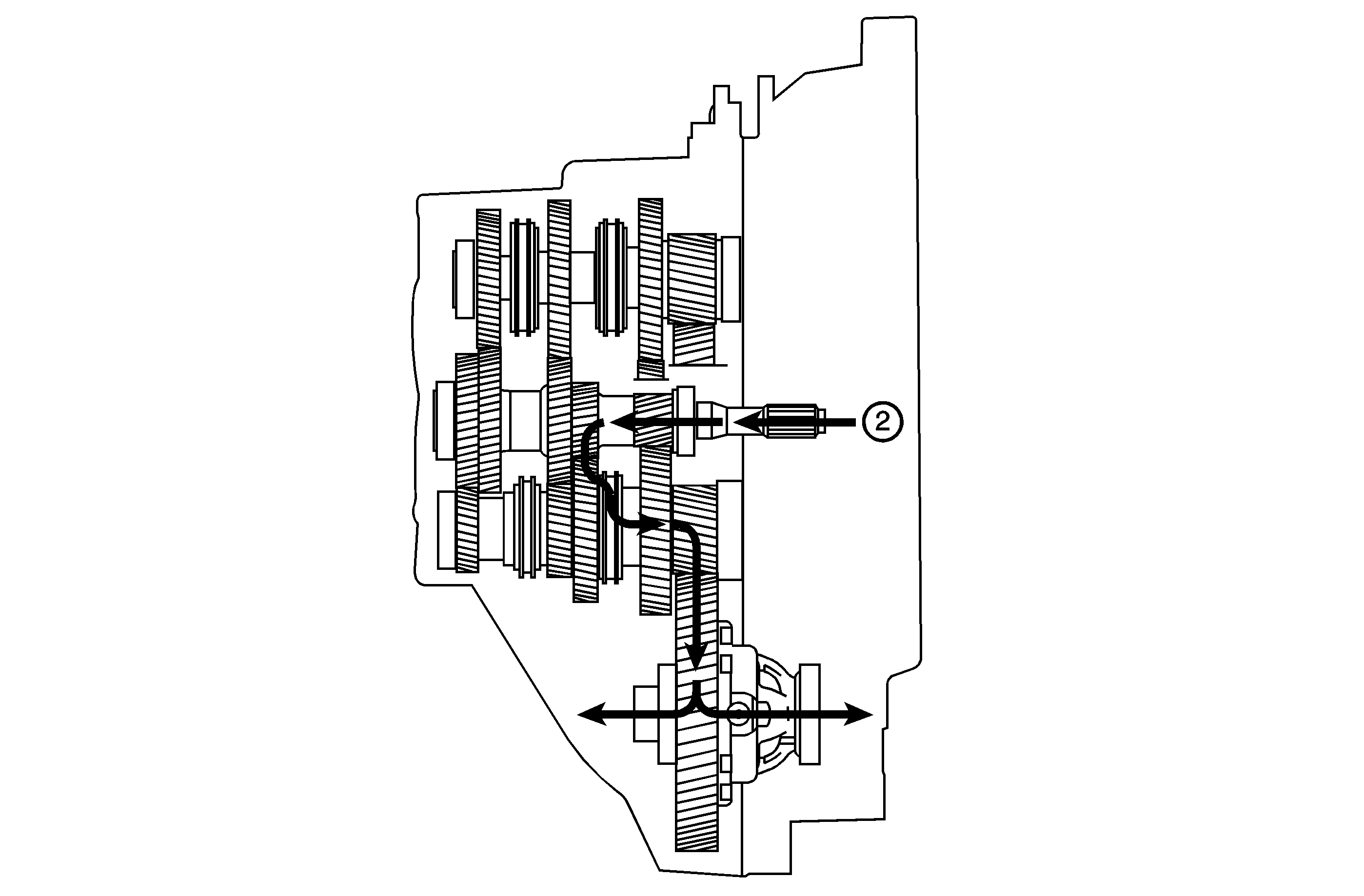
In 2nd gear range, power is transmitted via the 2nd gear pinion, fixed on the input shaft, to output shaft 1. 2nd gear wheel is locked to the output shaft 1, on which it is journalled, by the 1st/2nd synchronizer sleeve.
3rd Gear
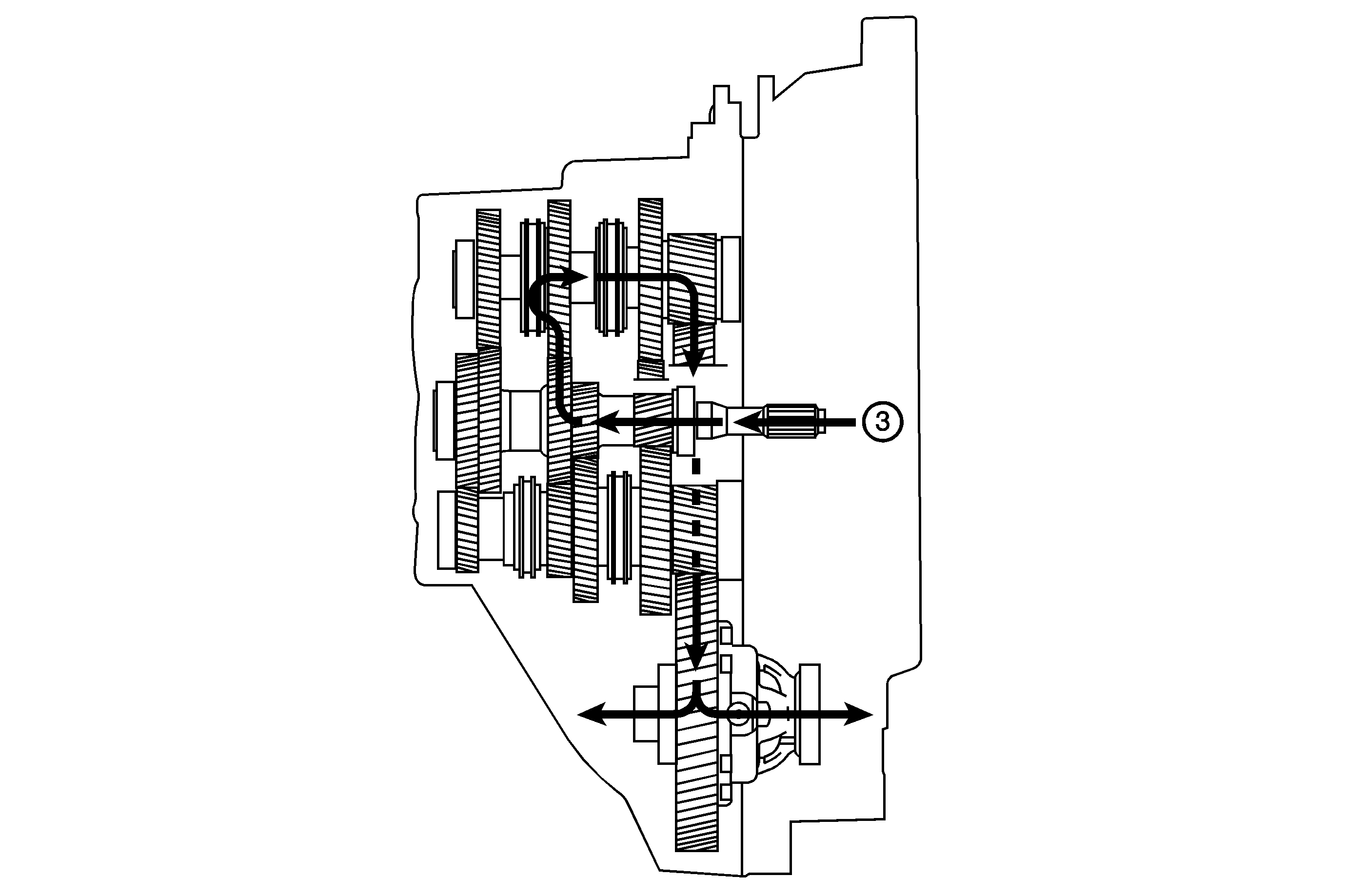
In 3rd gear range, power is transmitted via the 3rd/5th gear pinion, which is pressed over a splined joint on the input shaft, to output shaft 2. 3rd gear wheel is locked to the output shaft 2, on which it is journalled, by the 3rd/4th synchronizer sleeve.
4th Gear
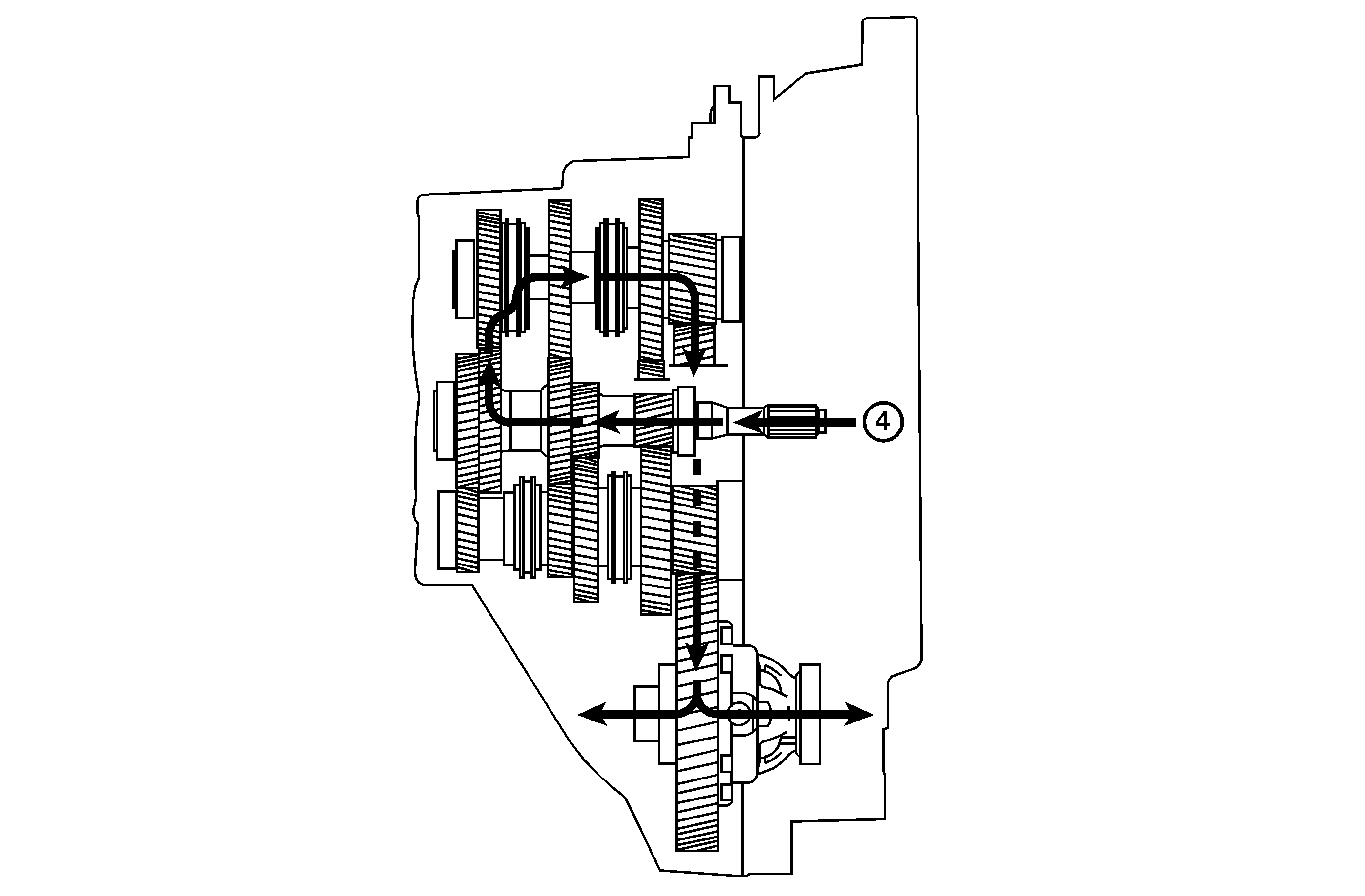
In 4th gear range, power is transmitted via the 4th gear pinion, which is pressed over a splined joint on the input shaft, to output shaft 2. 4th gear wheel is locked to the output shaft 2, on which it is journalled, by the 3rd/4th synchronizer sleeve.
5th Gear
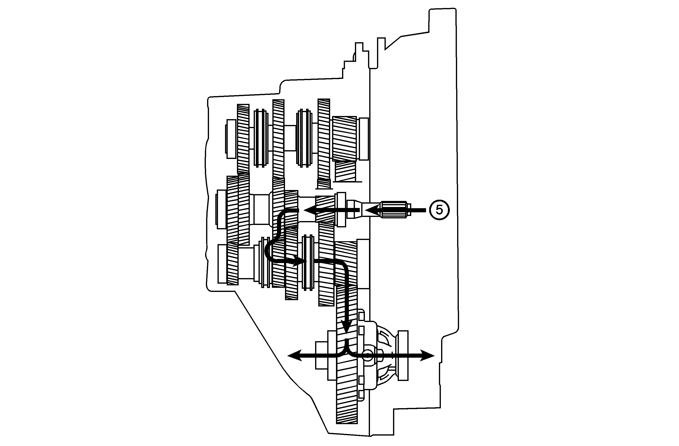
In 5th gear range, power is transmitted via the 3rd/5th gear pinion, which is pressed over a splined joint on the input shaft, to output shaft 2. 5th gear wheel is locked to the output shaft 1, on which it is journalled, by the 5th/6th synchronizer sleeve.
6th Gear
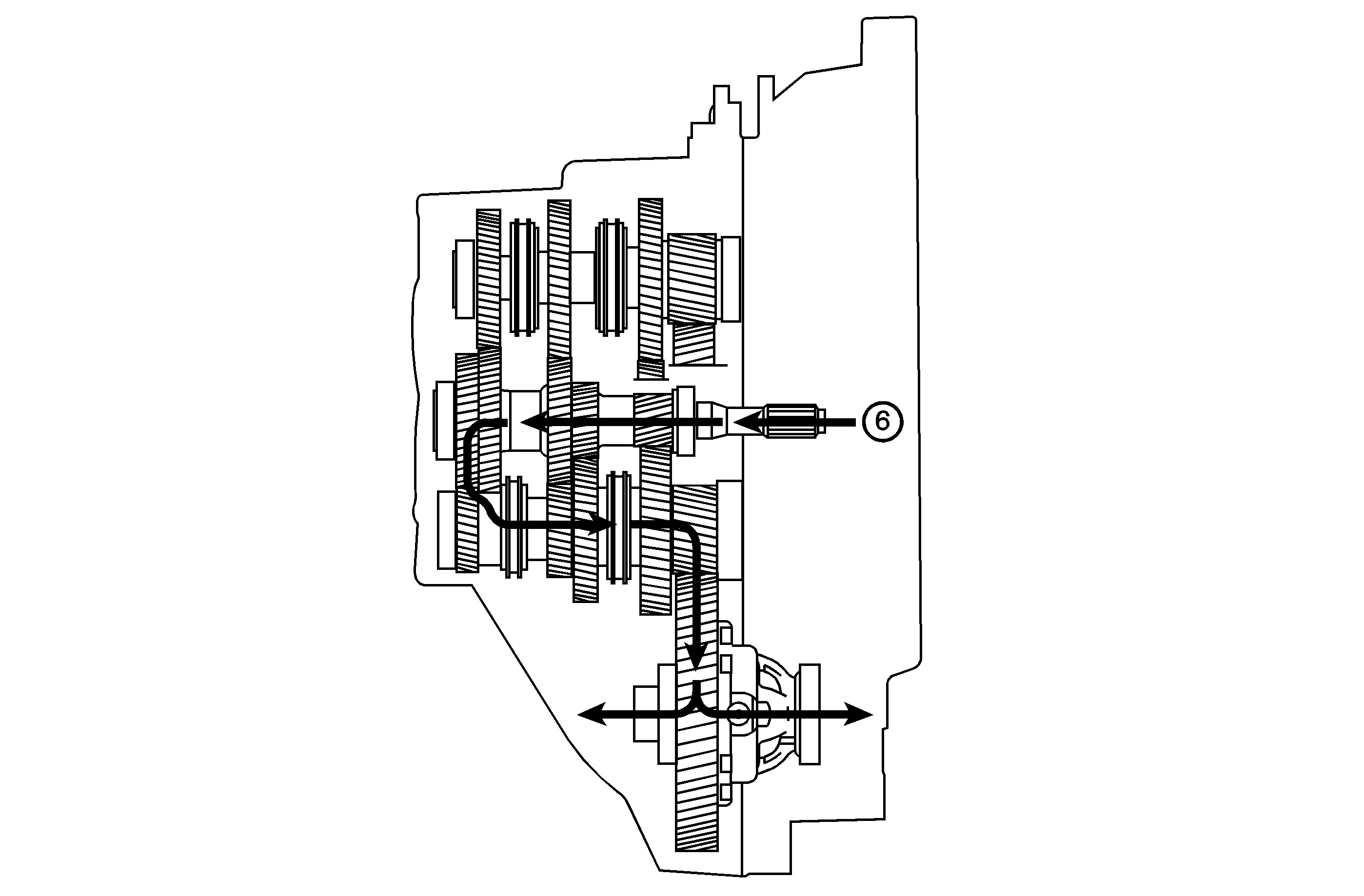
In 6th gear range, power is transmitted via the 6th gear pinion, which is pressed over a splined joint on the input shaft, to output shaft 1. 6th gear wheel is locked to the output shaft 1, on which it is journalled, by the 5th/6th synchronizer sleeve.
Reverse
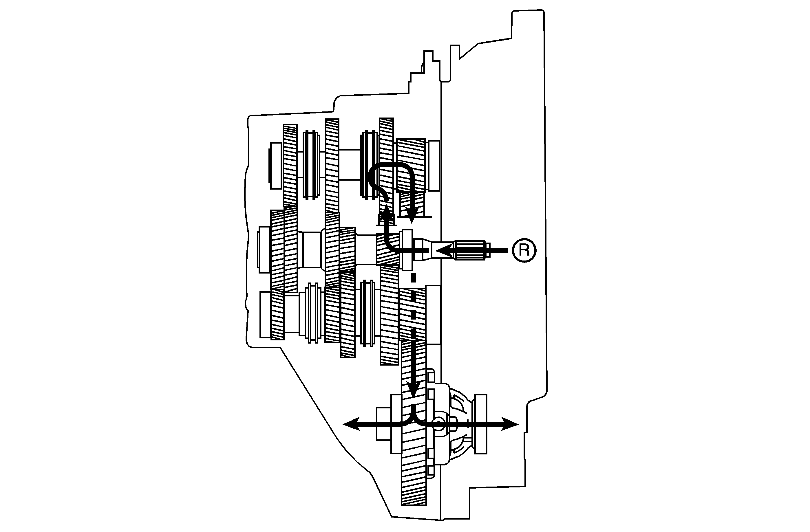
In reverse gear range, the power is transmitted from the 1st gear pinion on the input shaft to the 1st gear wheel on the lower output shaft. This is in constant mesh with the reverse gear wheel that is journalled on the upper output shaft. When the reverse gear sleeve locks the reverse gear wheel to the output shaft, reverse is achieved with the 1st gear wheel acting as an idler gear.
The gear ratios are as follows:
Gear | MU9 Ratio (1:1) |
|---|---|
FIRST | 3.77 |
SECOND | 2.04 |
THIRD | 1.37 |
FOURTH | 1.05 |
FIFTH | 0.85 |
SIXTH | 0.71 |
REVERSE | 3.54 |
