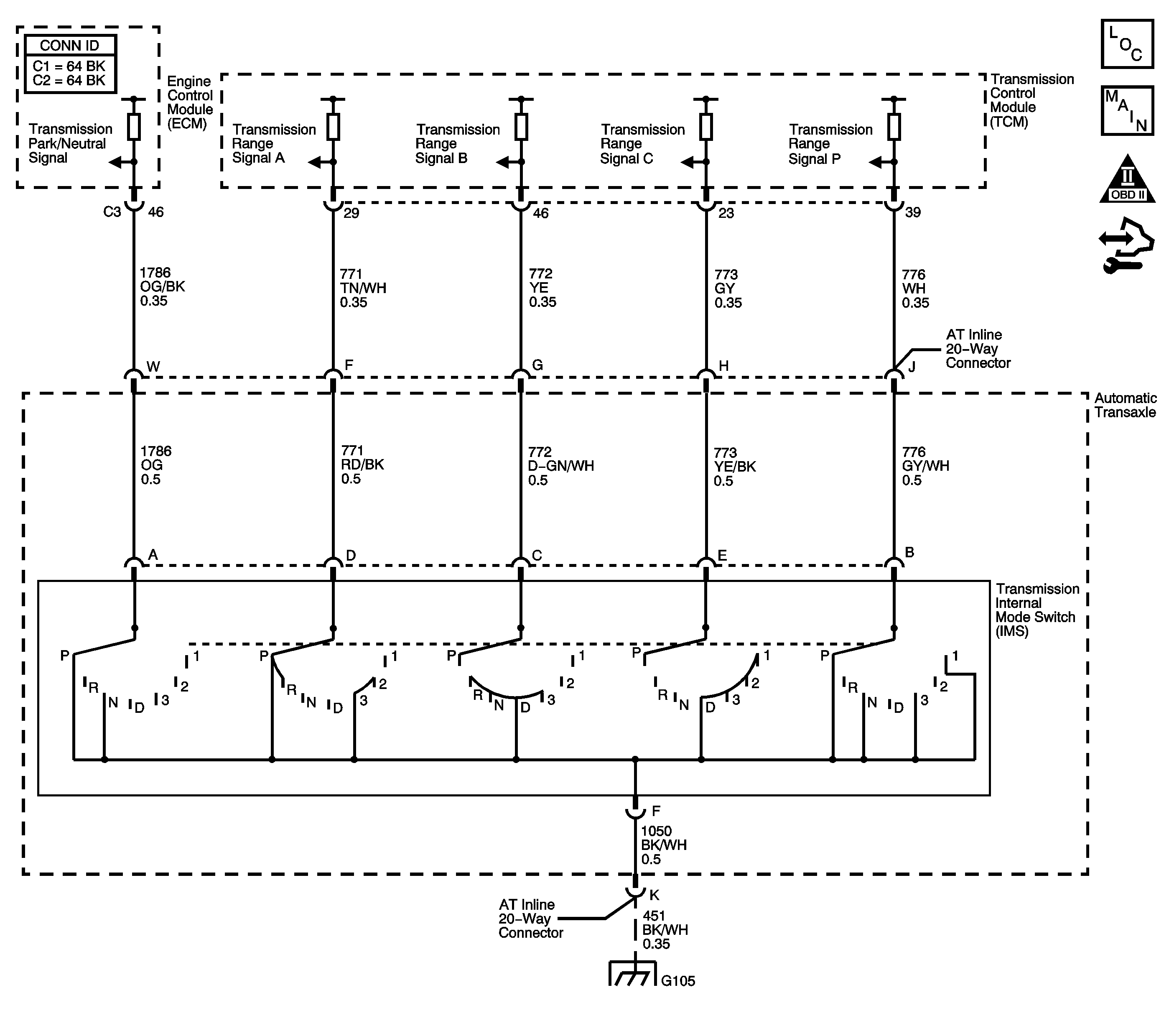
Circuit Description
The engine control module (ECM) provides 12-volts to the park/neutral position (PNP) switch of the manual shift shaft position switch. The manual shift shaft position switch is a sliding contact assembly that attaches to the manual shift shaft inside the transmission. The switch consists of 5 separate circuits, 4 of which indicate gear selector position to the transmission control module (TCM), and 1 that indicates park/neutral position to the ECM. When the transmission is in PARK or NEUTRAL, the switch closes and pulls the ECM voltage low, 0-volts. When the transmission is not in PARK or NEUTRAL, the ECM voltage is high, 12-volts. The ECM uses the switch in order to enable starter operation.
If the PNP switch and the transmission manual shift shaft position switch do not agree for a specified length of time, DTC P0852 sets. DTC P0852 is a type C DTC.
DTC Descriptor
This Diagnostic procedure supports the following DTC:
DTC P0852 Park/Neutral Position (PNP) Switch Circuit High Voltage
Conditions for Running the DTC
| • | No communication DTCs U0073, U0100, U0121 or U0140. |
| • | No TPS DTCs P0120 or P0220. |
| • | No OSS DTCs P0722 or P0723. |
| • | The ignition voltage is 9-18-volts. |
| • | The engine speed is 400 RPM or greater. |
Conditions for Setting the DTC
The PNP switch is closed for 3.2 seconds while the TCM is reporting the gear selector is not in PARK or NEUTRAL.
Action Taken When the DTC Sets
| • | The ECM does not illuminate the malfunction indicator lamp (MIL). |
| • | The ECM uses the transmission range data to enable engine cranking. |
| • | The ECM records the operating conditions when the Conditions for Setting the DTC are met. The ECM stores this information as Failure Records. |
| • | The ECM stores DTC P0852 in ECM history. |
Conditions for Clearing the MIL/DTC
| • | The ECM clears the driver information center (DIC) message when the condition no longer exists. |
| • | A scan tool can clear the DIC/DTC. |
| • | The ECM clears the DTC from ECM history if the vehicle completes 40 warm-up cycles without a non-emission-related diagnostic fault occurring. |
| • | The ECM cancels the DTC default actions when the ignition switch is OFF long enough in order to power down the ECM. |
Step | Action | Values | Yes | No | ||||
|---|---|---|---|---|---|---|---|---|
1 | Did you perform the Diagnostic System Check - Vehicle? | -- | Go to Step 2 | |||||
2 |
Important:
Did you record TCM Failure Records for DTC U0073, U0100, U0121, or U0140? | -- | Go to Step 3 | |||||
3 |
Does the PNP switch display Park/Neutral? | -- | Go to Testing for Intermittent Conditions and Poor Connections | Go to Step 4 | ||||
4 |
Does the PNP switch display Park/Neutral? | -- | Go to Step 6 | Go to Step 5 | ||||
5 | Test the PNP switch signal circuit for an open between the automatic transmission inline 20-way connector and the ECM. Refer to Testing for Continuity . Did you find and correct the condition? | -- | Go to Step 10 | Go to Step 9 | ||||
6 | Test the PNP Switch signal circuit for an open between the automatic transmission inline 20-way connector and the transmission internal mode switch. Refer to Testing for Continuity . Did you find the condition? | -- | Go to Step 7 | Go to Step 8 | ||||
7 | Replace the automatic transmission wiring harness. Refer to Wiring Harness Replacement in the Transmission Unit Repair Manual. Did you complete the replacement? | -- | Go to Step 10 | -- | ||||
8 | Replace the transmission internal mode switch. Refer to Manual Shift Detent Lever with Shaft Position Switch Assembly Removal in the Transmission Unit Repair Manual. Did you complete the replacement? | -- | Go to Step 10 | -- | ||||
9 | Replace the ECM. Refer to Control Module References for replacement, setup and programming. Did you complete the replacement? | -- | Go to Step 10 | -- | ||||
10 | Perform the following procedure in order to verify the repair:
Has the test run and passed? | -- | Go to Step 11 | Go to Step 2 | ||||
11 | With the scan tool, observe the stored information, capture info and DTC info. Does the scan tool display any DTCs that you have not diagnosed? | -- | System OK |
