For 1990-2009 cars only
Tools Required
J 45059 Angle Meter
Removal Procedure
- Relieve the fuel system pressure. Refer to Fuel Pressure Relief .
- Remove the intake manifold cover. Refer to Intake Manifold Cover Replacement .
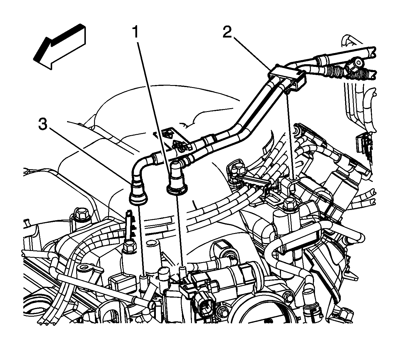
- Disconnect the fuel feed pipe (3) from the fuel rail. Refer to Metal Collar Quick Connect Fitting Service .
- Cap or plug the fuel feed pipe and the fuel rail in order to prevent system contamination.
- Open the upper retainer (1) and remove the fuel feed pipe from the retainer.
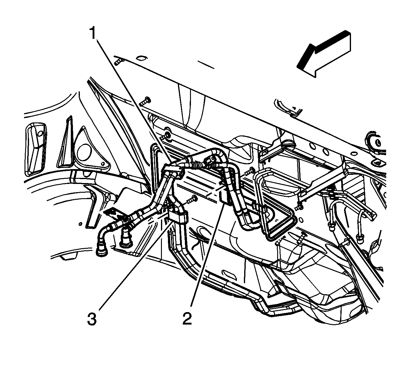
- Open the retainers (2, 3) attached to the studs on the front of dash and remove the fuel feed pipe.
- Raise and support the vehicle. Refer to Lifting and Jacking the Vehicle .
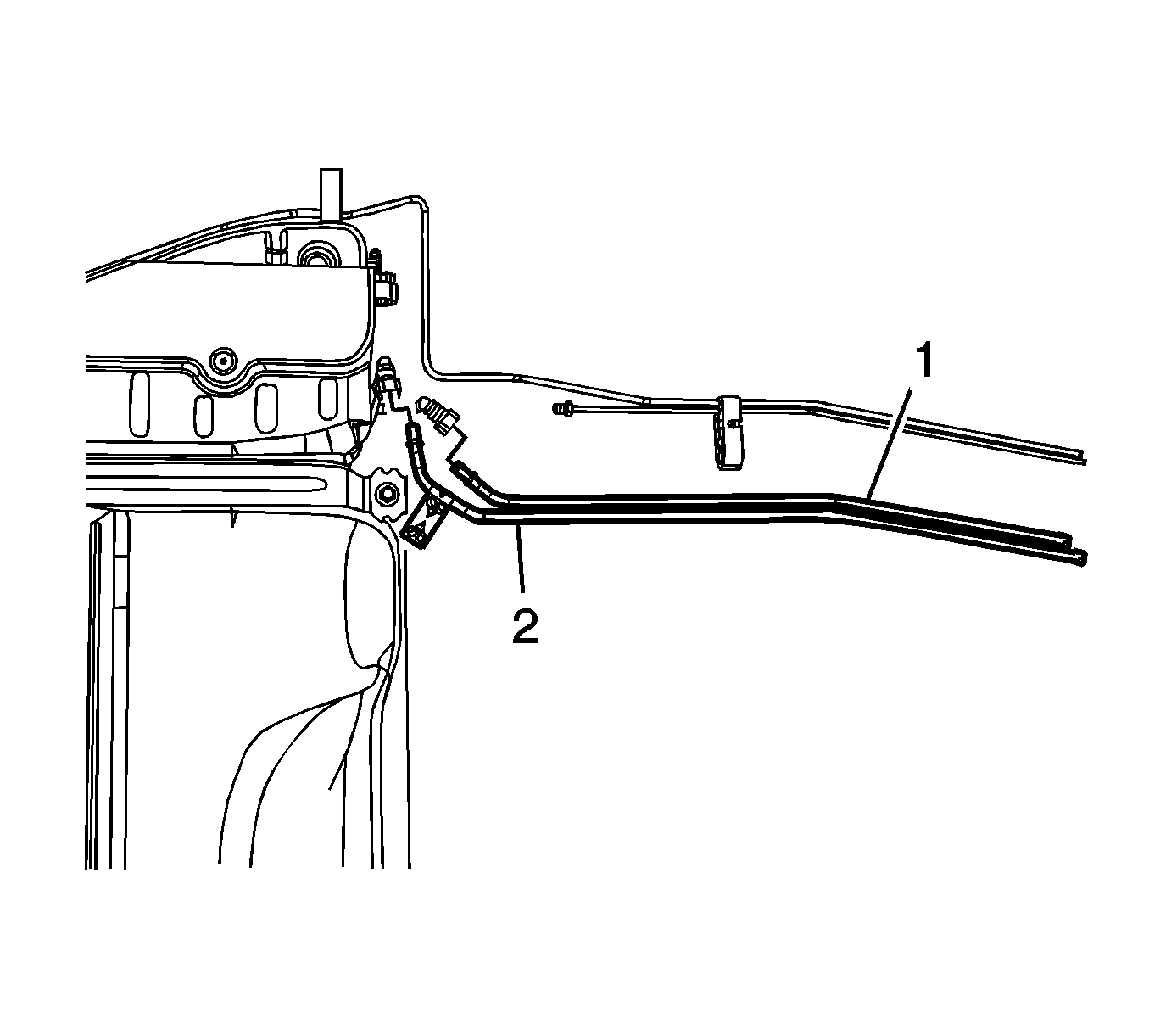
- Disconnect the fuel feed pipe (2) quick connect fitting from the fuel tank line. Refer to Plastic Collar Quick Connect Fitting Service .
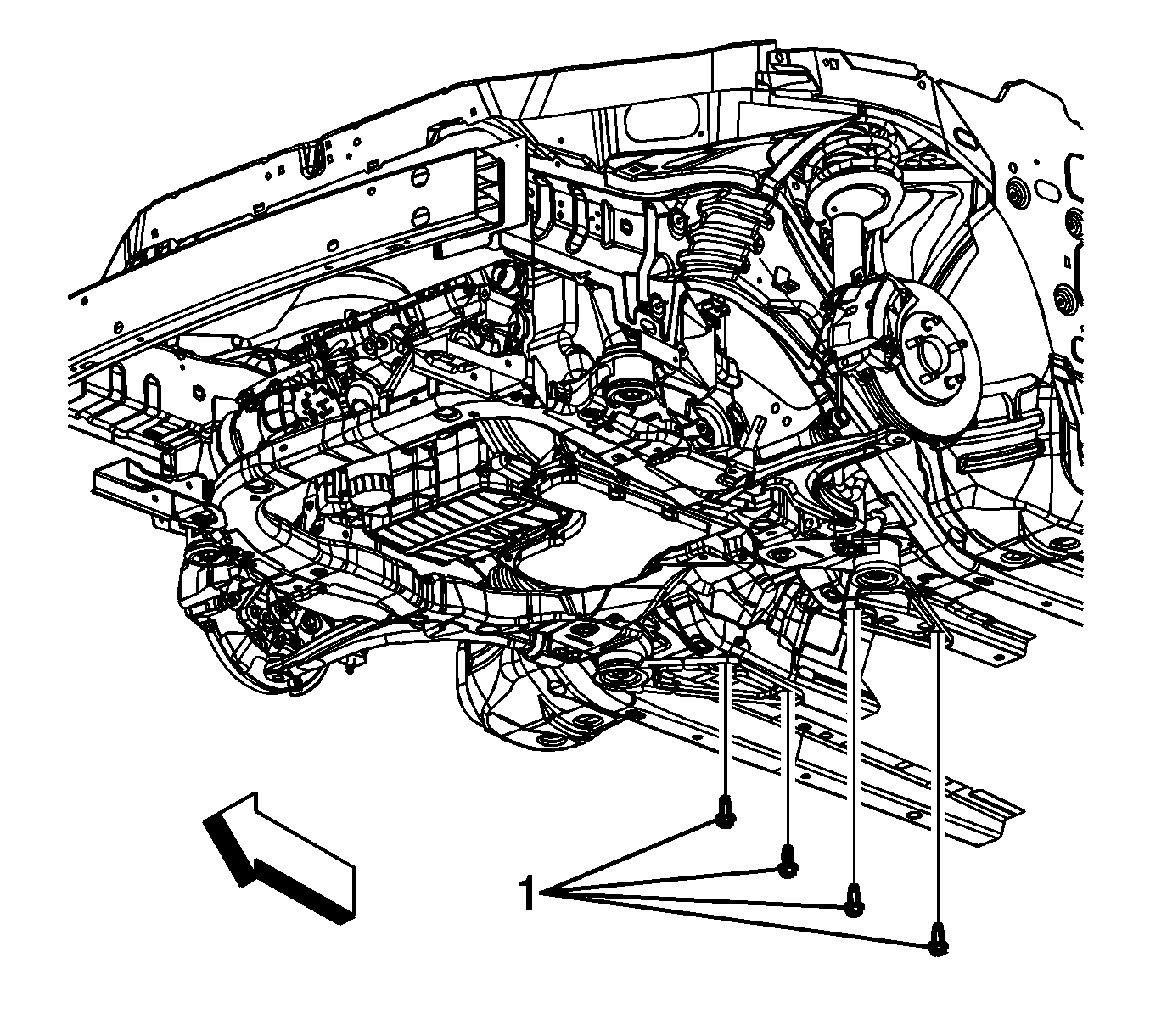
- Remove the side rail reinforcement bolts (1).
- Remove the front frame bolts (1).
- Remove the side rail reinforcements (3).
- Remove the rear brake pipe bracket nuts and release the brackets from the body studs.
- Release the pipe retainers from the vehicle underbody.
- Remove the fuel feed pipe from the pipe retainers.
- Lower the rear of the pipe while moving the pipe rearward slightly, then lower the front of the pipe.
- Remove the fuel feed pipe from the vehicle.

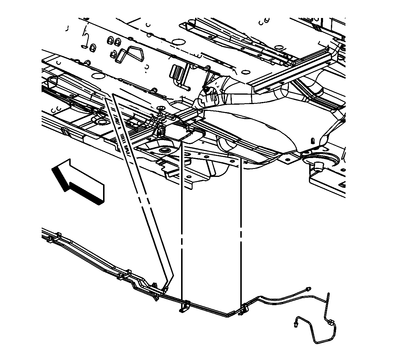
Installation Procedure
- Position the fuel feed pipe to the vehicle.
- With the rear of the pipe positioned slightly rearward and down, raise the front of the pipe into position.
- Install the remainder of the pipe into position.
- Install the fuel feed pipe to the pipe retainers.
- Secure the pipe retainers to the vehicle underbody.
- Position the side rail reinforcements (3) to the side rail and frame.
- Install the front frame bolts (1).
- Install the side rail reinforcement bolts (1).
- Connect the fuel feed pipe (2) quick connect fitting to the fuel tank line. Refer to Plastic Collar Quick Connect Fitting Service .
- Lower the vehicle.
- Remove the caps or plugs from the fuel pipe and the fuel rail.
- Install the fuel feed pipe to the retainers (2, 3) and close the retainers.
- Install the fuel feed pipe to the upper retainer (1) and close the retainer.
- Connect the fuel feed pipe (2) to the fuel rail. Refer to Metal Collar Quick Connect Fitting Service .
- Connect the negative battery cable. Refer to Battery Negative Cable Disconnection and Connection .
- Inspect for fuel leaks using the following procedure:
- Install the intake manifold cover. Refer to Intake Manifold Cover Replacement .


Notice: Refer to Fastener Notice in the Preface section.
Tighten
Tighten the bolts to 100 N·m (73 lb ft) plus an additional 180 degrees using
J 45059
.

Tighten
Tighten the bolts to 50 N·m (37 lb ft).


| 16.1. | Turn ON the ignition, with the engine OFF for 2 seconds. |
| 16.2. | Turn OFF the ignition for 10 seconds. |
| 16.3. | Turn ON the ignition, with the engine OFF. |
| 16.4. | Inspect for fuel leaks. |
