Clutch Rotor and/or Bearing Install V7 - Direct Mount
Tools Required
| • | J 33013-B Hub
and Drive Plate Remover/Installer |
| • | J 33017 Pulley
and Bearing Assembly Installer |
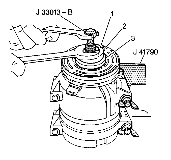
- Position the clutch rotor
and bearing assembly (2) onto the A/C compressor.
- Position the J 33017
and bearing (1) from the J 33013-B
directly over the inner race of the bearing.
- Place the washer (3) from the J 42126 tool kit onto the
body of the J 33013-B
.
- Remove the center screw from the body of the J 33013-B
.
- Install the center screw into the opposite end of the J 33013-B
.
- Back the body of the J 33013-B
off enough to allow the center screw to be threaded onto
the end of the A/C compressor shaft.
- Thread the center screw several turns onto the end of the A/C
compressor shaft.
Do not tighten the center screw on the A/C compressor shaft.
- Hold the center screw with a wrench.
- Tighten the hex portion of the J 33013-B
body several turns.
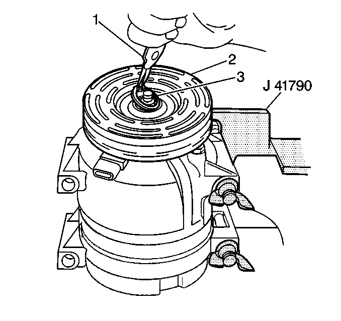
- Remove the J 33013-B
from the clutch rotor and bearing
assembly.
- Make sure that the clutch rotor and bearing (2) is pressed onto
the nose of the A/C compressor far enough to clear the groove for the retaining
ring.
If the clutch rotor and bearing does not clear the groove, repeat steps
7, 8 and 9.
- Install the clutch rotor and bearing retaining ring (3)
using external snap ring pliers (1).
Make sure that the camphor side of the retaining ring is facing up when
the retaining ring is being installed.
- Install the clutch plate and hub assembly. Refer to A/C compressor Clutch Plate/Hub Assembly Install (V7 - Direct Mount)
.
- Remove the A/C compressor from the J 41790-A
.
- Install the A/C compressor into the vehicle.
Clutch Rotor and/or Bearing Install V5 - Conventional Mount
Tools Required
| • | J 6083 #24 External Snap
Ring Pliers |
| • | J 33017 Pulley And Bearing
Assembly Installer |
| • | J 34992 Compressor Holding
Fixture |
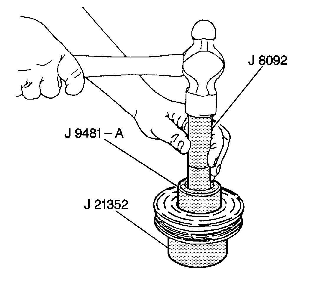
Notice: Do not support the rotor by resting the pulley rim on a flat surface
during the bearing installation or the rotor face will be bent.
- Place the
pulley rotor on the J 21352-A
in order to
fully support the rotor hub during the bearing installation.
- Align the new bearing with the hub bore.
- Using the J 9481-A
and the J 8092
, drive the bearing into the hub.
The J 9481-A
applies force to the
outer race of the bearing.
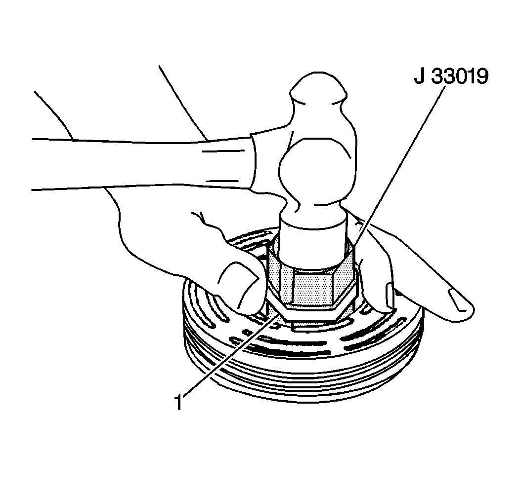
- Place the J 33019
and
the staking pin in the hub bore.
- Shift the rotor and bearing assembly on the J 21352-A
in order to fully support the hub under the location
of the staking pin.
- Use a heavy-duty rubber band (1) in order to hold the stake
pin in the guide of the J 33019
.
Important: Do not allow a metal stake to contact the outer face of the bearing
in order to prevent distortion of the outer race.
- Using care in order to prevent injury, strike the staking pin of the J 33019
. Properly position the stake pin in
the guide after each impact on the pin.
- Continue to strike the pin of the J 33019
until a stake, similar to the original stake, is formed down to, but not touching,
the bearing.
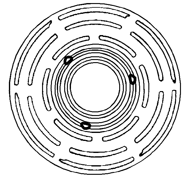
- Stake 3 places 120 degrees apart.
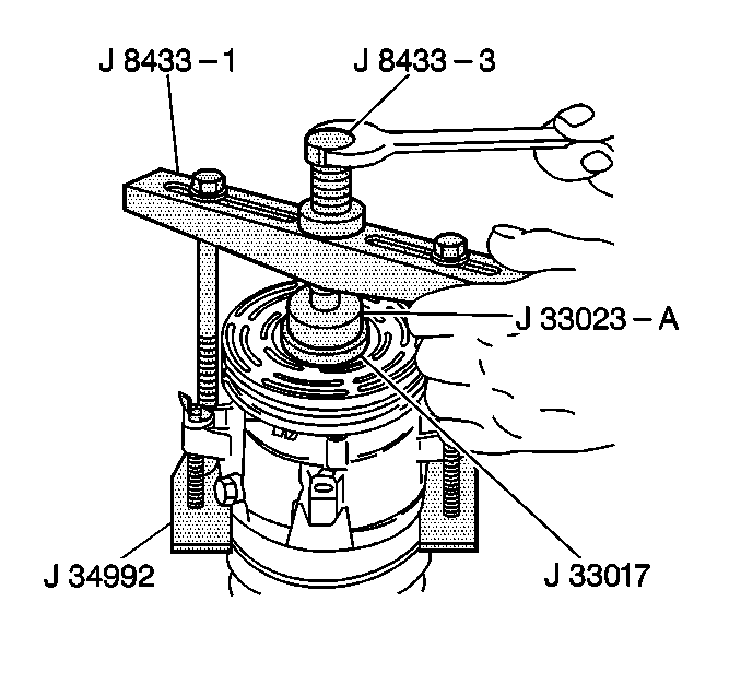
- With the compressor mounted to the J 34992
, position the rotor and bearing assembly
on the front head.
- Position the J 33017
and the J 33023-A
directly over the inner race of the bearing.
- Position the J 8433-1
on
the J 33023-A
.
- Assemble the 2 through bolts and the washers of the J 34992
through the slots of the J 8433-1
.
- Thread the 2 through bolts into the J 34992
.
Ensure that the thread of the through bolts engages the full
thickness of the J 34992
.
- Tighten the J 8433-3
in the J 8433-1
in order to force the pulley rotor
and bearing assembly onto the front head of the compressor.
- If the J 33017
slips off direct,
in-line contact with inner face of the bearing, use the following steps:
| 16.2. | Realign the J 33017
and the J 33023-A
in order to ensure that the installer
clears the front head. |
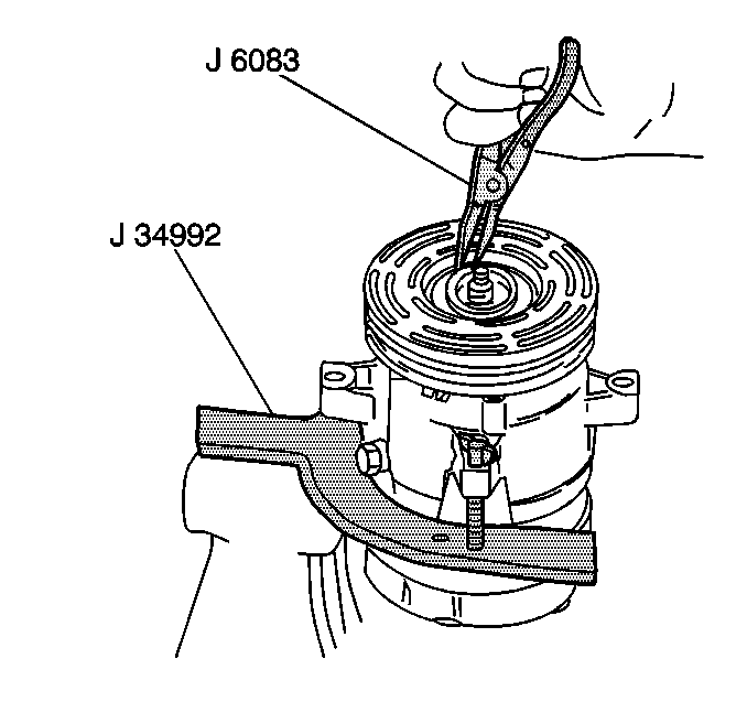
- Install the rotor and bearing assembly
retainer ring using the J 6083
.
- Install the clutch plate and hub assembly. Refer to
Compressor Clutch Plate/Hub Assembly Install
.


