CONVERTIBLE ENHANCEMENTS NOISE, SEATBELT TRIM, OPERATE

SUBJECT: CONVERTIBLE ENHANCEMENTS - NOISE, SEAT BELT TRIM OPERATING AND LEAK ISSUES (DIAGNOSTIC/REPAIR INFORMATION)
MODELS AFFECTED: 1991-92 FIREBIRD CONVERTIBLE MODELS
CONDITION:
---------- The following bulletin addresses eleven issues which are divided into four categories: 1) noise related; 2) seat belt quarter trim cap issues; 3) operating issues; and 4) leak issue.
NOTE: To avoid damage when lowering or raising the convertible top, refer to the 1992 Service Manual Section 10-8 for proper procedures.
NOISE RELATED (I)
Application: VIN Breakpoints: NL200310
CONDITION:
---------- The following three conditions may exist causing squeak and rattle in the number one bow area.
(1) Rattle between the number one bow and the side rails.
(2) Squeak between number one bow and number one bow garnish molding.
(3) Rattle between number one bow boss and number two bow pivot link.
CORRECTION:
-----------
Perform all the following corresponding corrections.
CORRECTION FOR CONDITION (1):
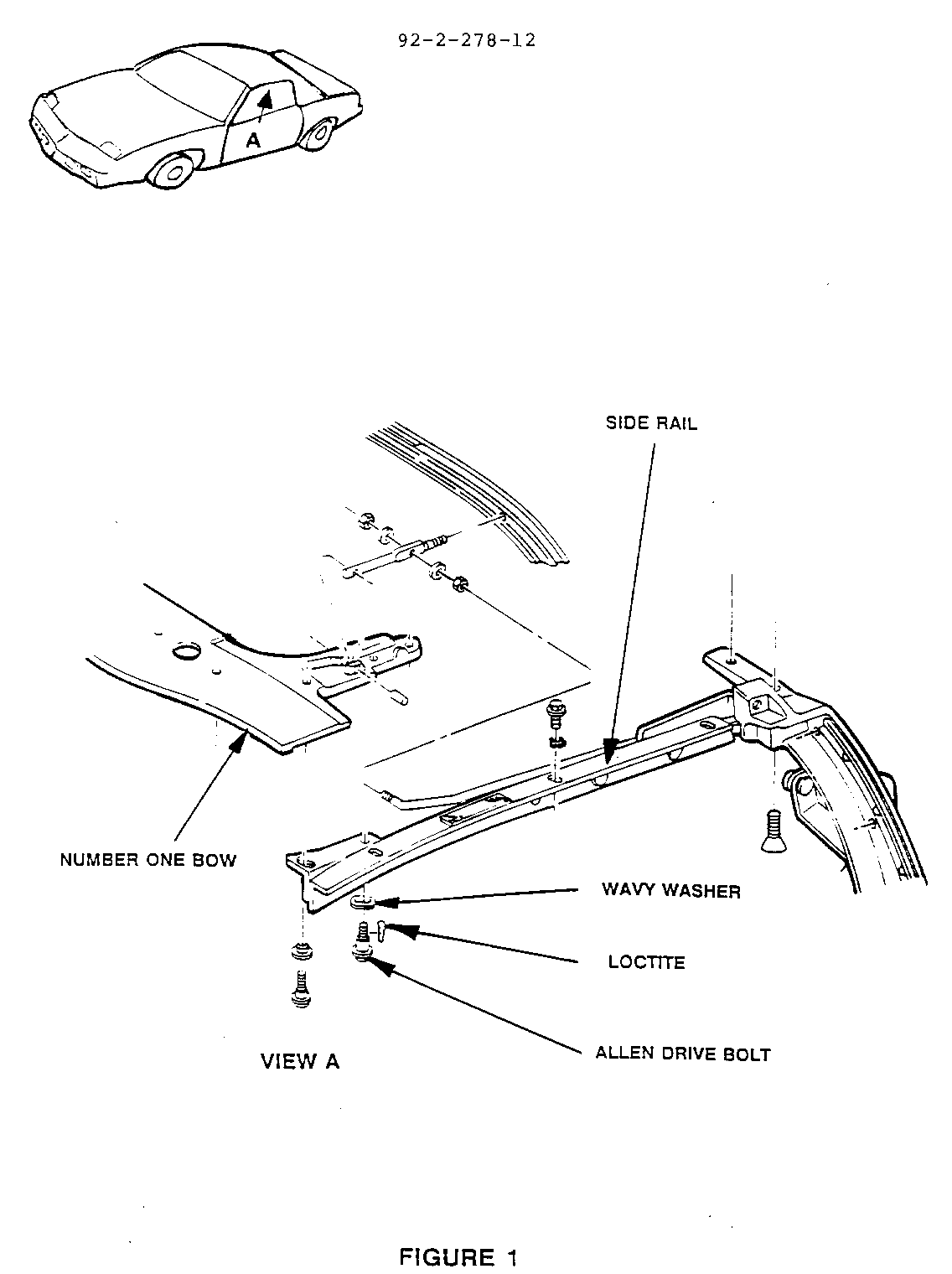
Add a wave washer P/N 12520633 and *Loctite Removable Threadlocker #242 to provide tighter fit of number one bow and side rails.
1. Lower the top halfway. Refer to 1992 Service Manual Section 10-8 for removal of the number one bow garnish molding and remove.
2. Refer to Figure 1, left side view shown, right side similar. Remove Allen drive bolt, one per side, attaching side rails to number one bow.
NOTICE: Do not remove both Allen drive bolts at the same time. Reinstallation would be more difficult.
3. Add one washer P/N 12520633 to each bolt and apply Loctite Removable Threadlocker #242 to the threads.
4. Reinstall bolts with washers and Loctite.
CORRECTION FOR CONDITION (2):
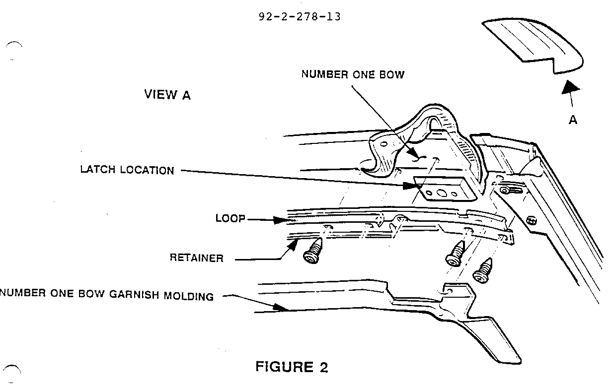
Replace foam tape on the top cover retainer with loop portion of *3M #06480 Scotchmate Hook and Loop Fastening System. Cut strip in half and install a strip inboard of each latch location. (Refer to Figure 2).
1. Remove old foam tape from garnish molding.
2. Refer to Figure 2 which shows an exploded assembly, but only the garnish molding needs to be removed to access the old tape. Cut loop portion, of 3M #6480 Hook and Loop Fastening System, in half and install a strip inboard of each latch location along the length of the top cover retainer.
3. Trim away any excess "loop" material.
CORRECTION FOR CONDITION (3):
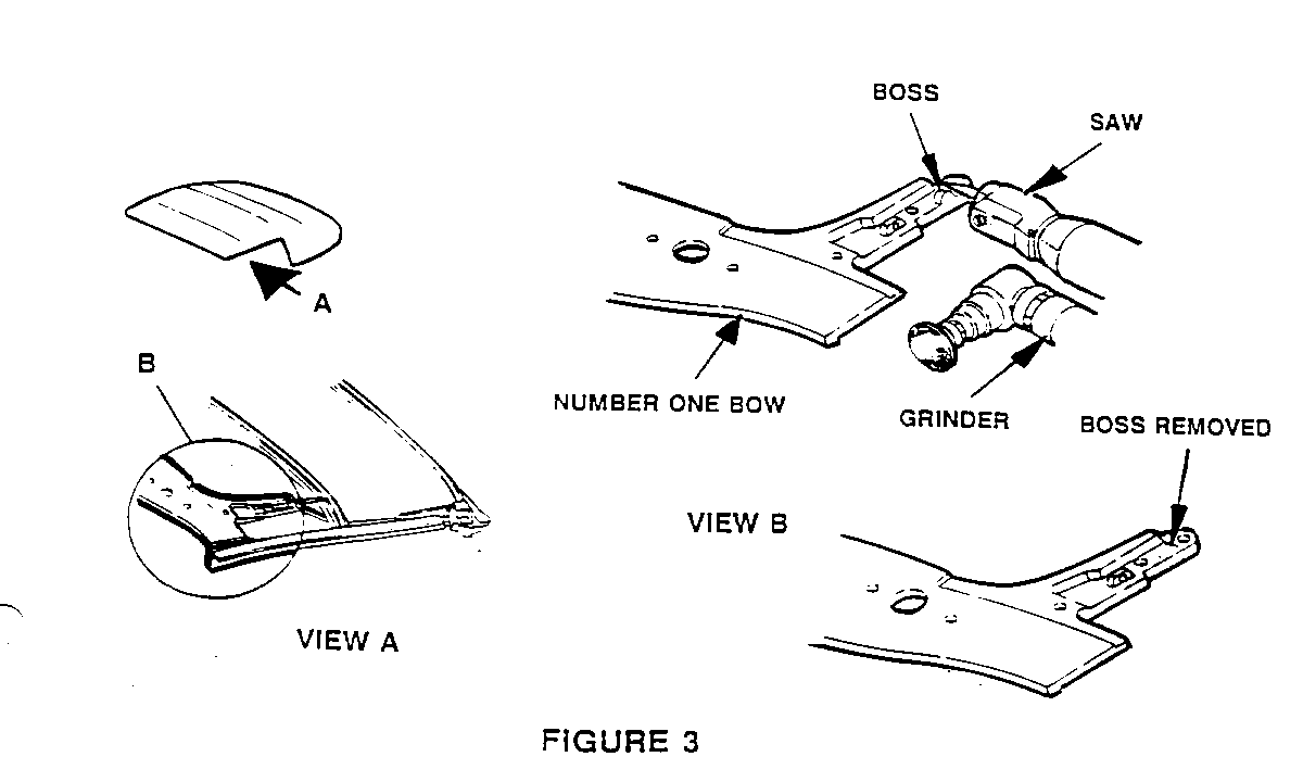
Saw or grind off boss. File any burrs and paint cut area.
NOTICE: Protect top cover, backlite and any exposed surfaces from metal filings. Use cardboard and tape, paint drop cover, etc. to protect exposed surfaces.
1. Refer to Figure 3. Locate bosses at the rear outboard sides of number one bow. Use a small air body saw or 90 degree grinder to remove the bosses. Cut flush to the number one bow surface.
2. File any burrs or rough areas. Use black exterior touch-up paint P/N 1050335 on the cut/ground areas. Follow paint instructions for drying time.
3. Install garnish molding.
4. Raise and latch the top.
LABOR OPERATION: T1869 TIME ALLOWANCE: 1.3 HRS. Total Time
NOISE RELATED (II)
Application: 1991
CONDITION:
---------- Squeak at header inner trim garnish molding.
CORRECTION:
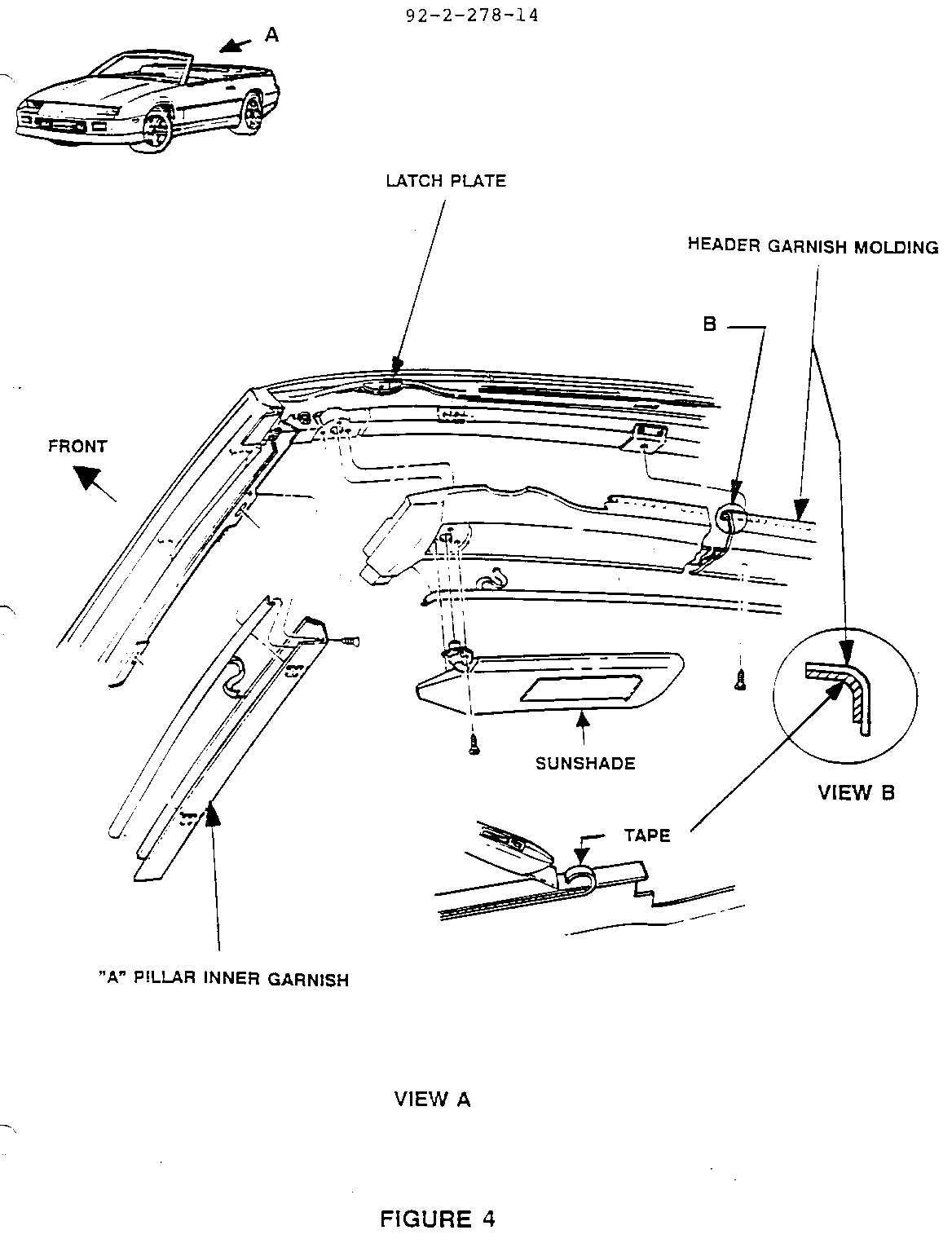
----------- Add 546 mm (21.5") of 3M #5430 Squeak Reduction tape to garnish molding.
1. Refer to Figure 4. Remove sunshade screws and sunshade.
2. Remove header inner trim garnish molding screw.
NOTICE: Use care to prevent cracking or marring of garnish molding during removal and reinstallation.
3. Loosen "A" pillar inner garnish molding upper screw (left and right side).
4. Carefully shift header garnish molding rearward and out of the latch plate. Then slide header garnish molding up and out of the "A" pillar inner garnish molding.
5. Note Figure 4, View B. Apply 546 mm (21.5") of 3M #5430 tape to header garnish molding inner face between the latch plate locations.
6. Trim any tape protruding from the molding flange. Reinstall the header inner trim garnish molding.
7. Install and tighten "A" pillar inner garnish molding screws. Carefully shift edges of header garnish molding forward and between edges of the latch plates while slipping upper lip to outside of header edge. Install and tighten header garnish screw.
IMPORTANT: The sunshade should be mounted so that the larger pivot hole is nearest to the front of the vehicle when the sunshade is attached. Check the fit for the sunshade. The screws should fit in evenly with no difficulty.
8. Install sunshade aligning mounting holes, installing screws and tightening.
LABOR OPERATION: T1871 TIME ALLOWANCE: 0.6 HR.
NOISE RELATED (III)
Application: 1992
CONDITION:
---------- Number three bow snaps past number four bow when top is lowered and stowed.
CORRECTION:
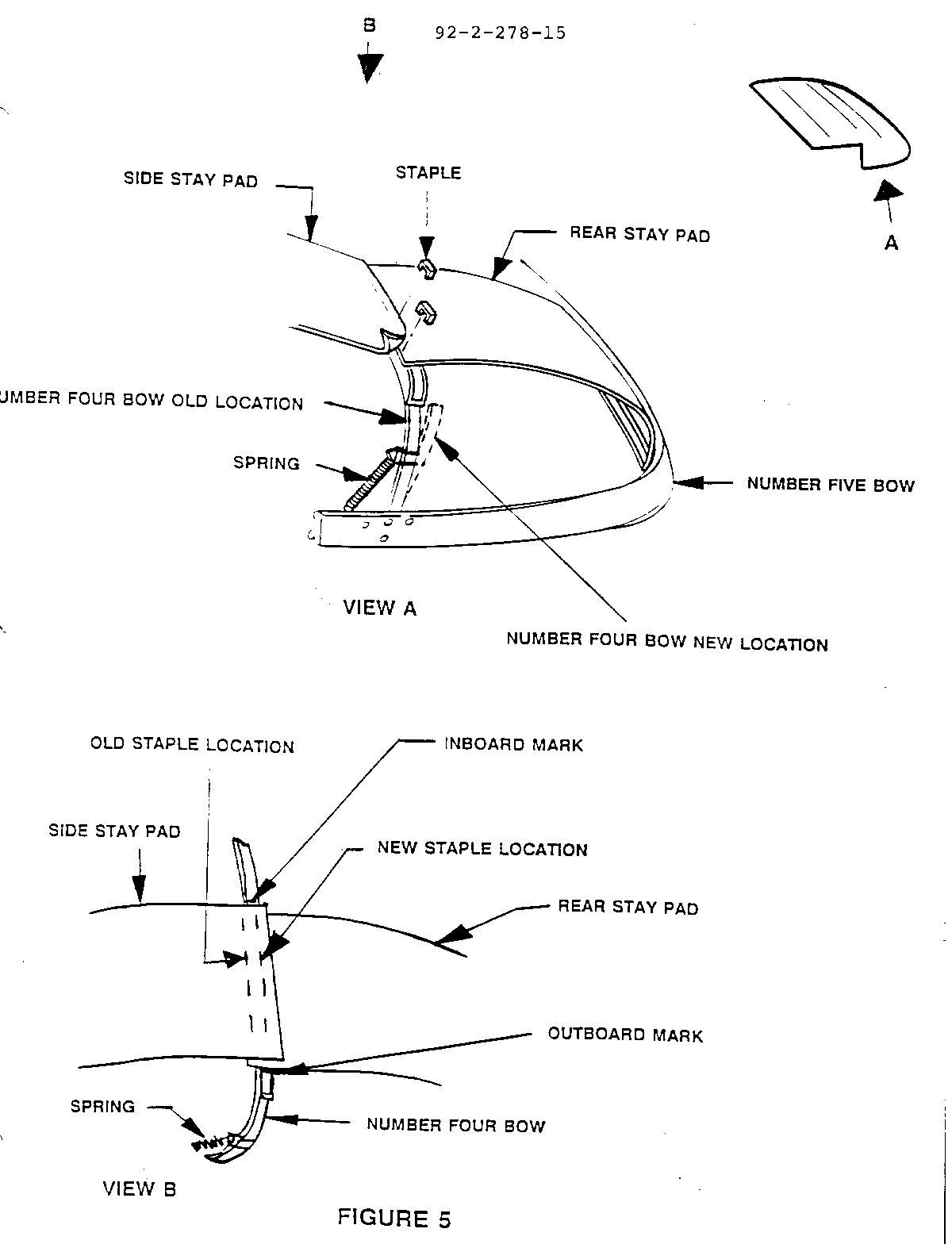
----------- Relocate number four bow. Refer to Figure 5.
1. Unlatch top at front header.
2. Unlatch and raise number five bow to vertical position and push forward.
3. Pull number four bow rearward of the number five bow. Number four bow springs will cause a toggle affect, holding it in this position.
4. To keep the number four bow rearward of the number five bow, place a wood block or equivalent between the number four and five bow at one side of the vehicle where the number four bow attaches to the number five bow.
5. Push the number four bow forward until the toggle action of the springs causes the bow to move forward and trap the wood block.
6. Both number four and five bows should now be forward of the number three bow.
7. This positioning will allow enough flexibility in the top cover to access the stay pads.
8. Mark the side stay pad staple locations with a grease pencil. Refer to Figure 5. Mark number four bow on the inboard side of pad. This will aid positioning of the pad at the new location.
9. Detach side stay pad staples from number four bow.
10. Mark staple locations on the rear stay pads with a grease pencil. Mark number four bow on outboard side of pad. This will aid positioning of the pad at the new location.
11. Detach rear stay pad staples from number four bow.
12. Measure and mark new staple locations 6.5 mm (1/4") rearward of old locations on both pads with a grease pencil.
13. Staple the rear and side stay pads (in that order) to the number four bow at the new staple locations, 6.5 mm (1/4") rearward, marked previously with a grease pencil. Note alignment marks on number four bow.
14. Remove wood block and toggle number four bow forward of number five bow.
15. Unlatch and raise tonneau to vertical position.
16. Lower top to ensure that snap is eliminated.
17. Raise and relatch top.
LABOR OPERATION: T1873 TIME ALLOWANCE: 0.6 HR.
SEAT BELT QUARTER TRIM CAP ISSUES (I)
Application: 1991-1992
CONDITION:
---------- Seat belt twisting at B-pillar trim cap in vehicles prior to 1992 VIN 203520.
CORRECTION:
----------- Replace both trim caps with P/N 12517754-5 right and left and bezels with P/N 12508710-11 right and left.
1. Completely lower convertible top.
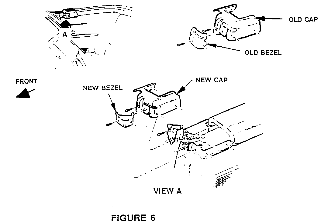
2. Refer to Figure 6. Remove attaching screws. Remove old quarter trim caps and shoulder belt bezels.
NOTE: Some vehicles may already have a new bezel and only need a new cap. If a new bezel is installed, make sure it is installed on the proper side.
3. Using new bezel as a template, mark locations and drill 3.0 mm (1/8") attaching holes in vehicle and new trim cap.
4. Install new cap P/N 12517754-5 and new bezel P/N 12508710-11. Match bezel with proper side to avoid improper fit and binding.
5. Check belts for smooth operation. Raise and latch top.
LABOR OPERATION: C4018 TIME ALLOWANCE: 1.0 HR. for Both
SEAT BELT QUARTER TRIM CAP ISSUES (II)
Application: 1991
CONDITION:
---------- Convertible topstack folding mechanism rubs against B-pillar trim cap.
CORRECTION:
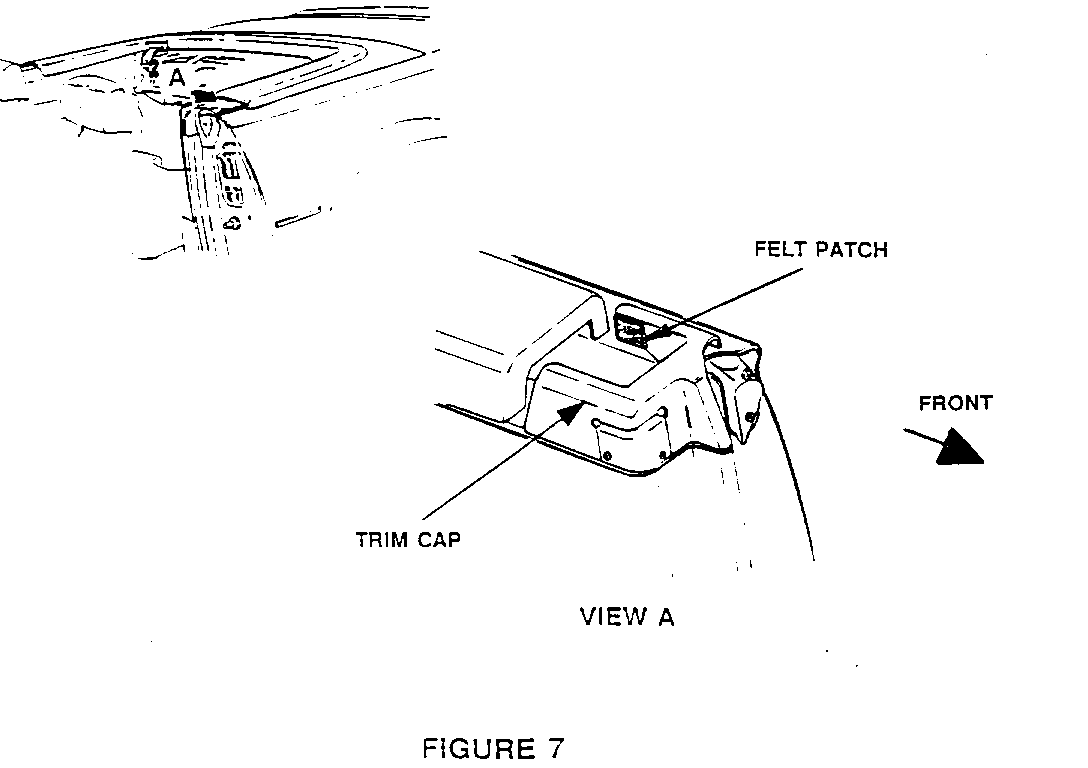
Add 25 mm (1") square piece of felt to both trim caps at rear of outboard surface. See Figure 7. The felt insulator material has adhesive backing and may be obtained from most local fabric stores. As an option use loop portion of 3M #06480 Scotchmate Hook and Loop Fastening System.
1. Lower top.
2. Install 25 mm (1") square piece of adhesive backed felt to quarter trim cap at rear of outboard surface. See Figure 7. Patch will overlap B-pillar trim cap.
3. Raise and latch top.
LABOR OPERATION: T1872 TIME ALLOWANCE: 0.2 HR. for Both
OPERATING ISSUES (I)
Application: 1991-1992
CONDITION:
---------- Tonneau (stowage lid) release sluggish or slow to release, prior to VIN 200553.
CORRECTION:
----------- Relocate solenoid and use new cadmium or zinc-plated screws P/N 12517487.
1. Refer to 1992 Service Manual, Section 10-6 "Quarter Trim Panel (Convertible)", and remove panel.
2. Remove cable mounting screws and remove electrical cable from clamps. Leave manual cable attached to clamp.
3. Remove solenoid mounting screws and discard.
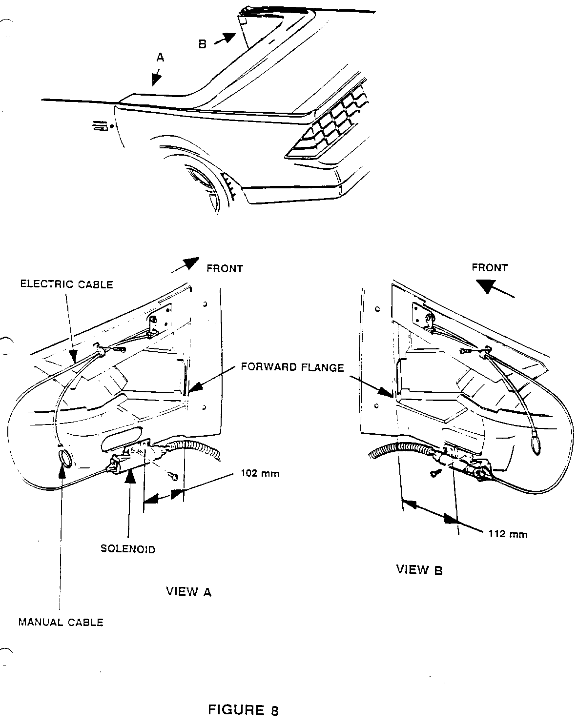
4. Refer to Figure 8. Relocate solenoid to new location.
NOTE: Check right or left orientation of bracket holes to mounting area. For best results, the solenoid forward hole is usually mounted on the inner panel 102 mm (4") left side and 112 mm (4.5") right side from the forward flange. Check clearances, cylindrical portion of solenoid must hang below the edge of the inner panel without interference.
The left hand solenoid must be positioned low enough to prevent interference with the solenoid plunger.
5. Mark new hole locations. Mount solenoid with new self drilling screws, P/N 12517487.
6. Attach electrical cable to clamp and mount. If a bind condition is noted after mounting cable, remove cable from clamp and allow to move freely.
7. Check operation of solenoid with quarter trim panel in position, before attaching panel with fasteners.
8. If needed, re-position cable elsewhere to assist smooth operation. Repeat above steps as necessary.
9. Reinstall the quarter trim panel.
LABOR OPERATION: T1870 TIME ALLOWANCE: 1.3 HRS. Both Sides
OPERATING ISSUES (II)
Application: 1991-1992
CONDITION:
---------- Tonneau panel and quarter cap belt molding protector decal (marnot tape) yellowing.
CORRECTION:
----------- Replace decals with Tonneau Protector Decal P/N 12520107 and Quarter Belt Cap Belt Molding Decal P/N 12520108-9 right and left.
1. For replacement of Tonneau Protector Decal refer to the 1992 Service Manual Section 10-8-19.
2. For replacement of Quarter Cap Belt Molding Decal refer to the 1992 Service Manual Section 10-6-7.
LABOR OPERATION: B3700 TONNEAU, B8235-6 QUARTER RH & LH TIME ALLOWANCE: 1.6 HRS. Total Time
OPERATING ISSUES (III)
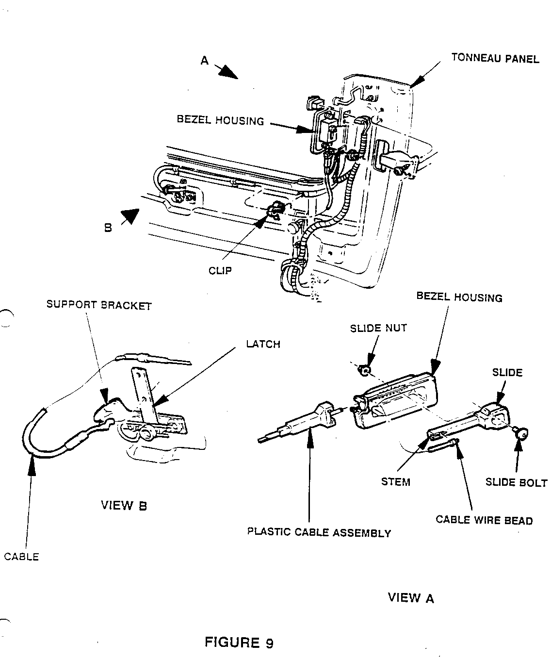
Application: 1991-1992
CONDITION:
---------- Number five bow release housing slide mechanism broken. 1992 VIN 246069.
CORRECTION:
----------- Replace bezel housing assembly and cable assembly with kit P/N 12517351.
1. Release and raise number five bow to its vertical position.
2. Release and raise tonneau to its vertical position.
3. Refer to Figure 9. Remove cable assembly from latch hole in number five bow latch and cable support bracket.
4. Remove support clips and cable. Support clips will be reused.
5. Remove bezel housing nuts and bezel housing with cable. Discard old bezel housing cable assembly.
6. Kit P/N 12517351 includes bezel housing, cable assembly, handle assembly (slide and stem), slide nut and slide bolt. This kit must be assembled.
7. Feed cable wire bead through _bezel housing and attach plastic cable assembly to housing.
8. Slide stem into bezel housing and place cable wire bead into recess of stem. Pull cable from opposite end for tension.
9. Attach bezel and nuts to tonneau.
10. Align cable assembly and clips to tonneau mounting holes and attach.
NOTE: The end of the cable near the number five bow latch must be correctly positioned to attach properly through the latch hole.
11. Attach cable assembly to latch hole in number five bow latch and to cable support bracket.
12. Secure slide to bezel housing with slide bolt and nut. Hand tighten bolt and nut.
13. Check cable operation. Repeat above procedure as necessary.
14. Lower tonneau and latch. Lower number five bow and latch.
LABOR OPERATION: B3640 TIME ALLOWANCE: 0.4 HR.
LEAK ISSUE
Application: 1991
CONDITION:
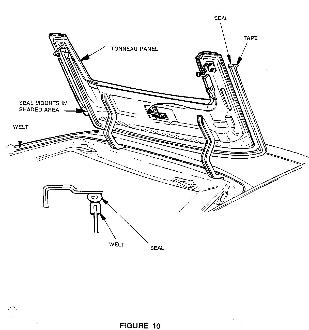
---------- Tonneau seal moves causing water leak.
CORRECTION:
----------- Replace tonneau seal with PIN 12511360.
1. Release and raise number five bow to its vertical position.
2. Release and raise tonneau to its vertical position.
3. Remove old tonneau seal by peeling gently away from tonneau panel and removing clips, if applicable.
4. Clean adhesive from tonneau panel using alcohol, oil free naphtha or 3M General purpose Adhesive Cleaner #08984 and follow manufacturer's directions for use.
CAUTION:
Avoid contacting marnot decal on opposite side with adhesive cleaner.
5. Refer to Figure 10.
NOTE: Tonneau seal should directly align with the trough welt to prevent water leaks. Center seal over welt.
6. Forward tabs of tonneau seal should align just past the edge of the tonneau panel.
7. Remove release liner from tape and loosely align new tonneau seal to the tonneau panel.
8. Close tonneau panel slowly and observe contact of seal so that it is over the center of the welt as shown in Figure 10.
9. Roll wall paper seam roller or equivalent over seal to bond it to the tonneau panel.
10. Lower and latch tonneau. Lower and latch number five bow.
11. Water test for proper sealing.
LABOR OPERATION: B3165 TIME ALLOWANCE: 0.7 HR.
* We believe these sources and their equipment to be reliable. There may be additional manufacturers of such equipment. General Motors does not endorse, indicate any preference for or assume any responsibility for the products or equipment from these firms or for any such items which may be available from other sources.
Part Availability:
Parts are expected to be available on August 31, 1992. In case of limited inventory, parts will be placed on 400 control to waive VIP surcharges. Only verifiable emergency VIP orders will be accepted. SPO will make every effort to obtain parts. However, the part will be shipped premium transportation at dealer's expense and all other order types will be placed on backorder until the 400 control is removed.
General Motors bulletins are intended for use by professional technicians, not a "do-it-yourselfer". They are written to inform those technicians of conditions that may occur on some vehicles, or to provide information that could assist in the proper service of a vehicle. Properly trained technicians have the equipment, tools, safety instructions and know-how to do a job properly and safely. If a condition is described, do not assume that the bulletin applies to your vehicle, or that your vehicle will have that condition. See a General Motors dealer servicing your brand of General Motors vehicle for information on whether your vehicle may benefit from the information.
