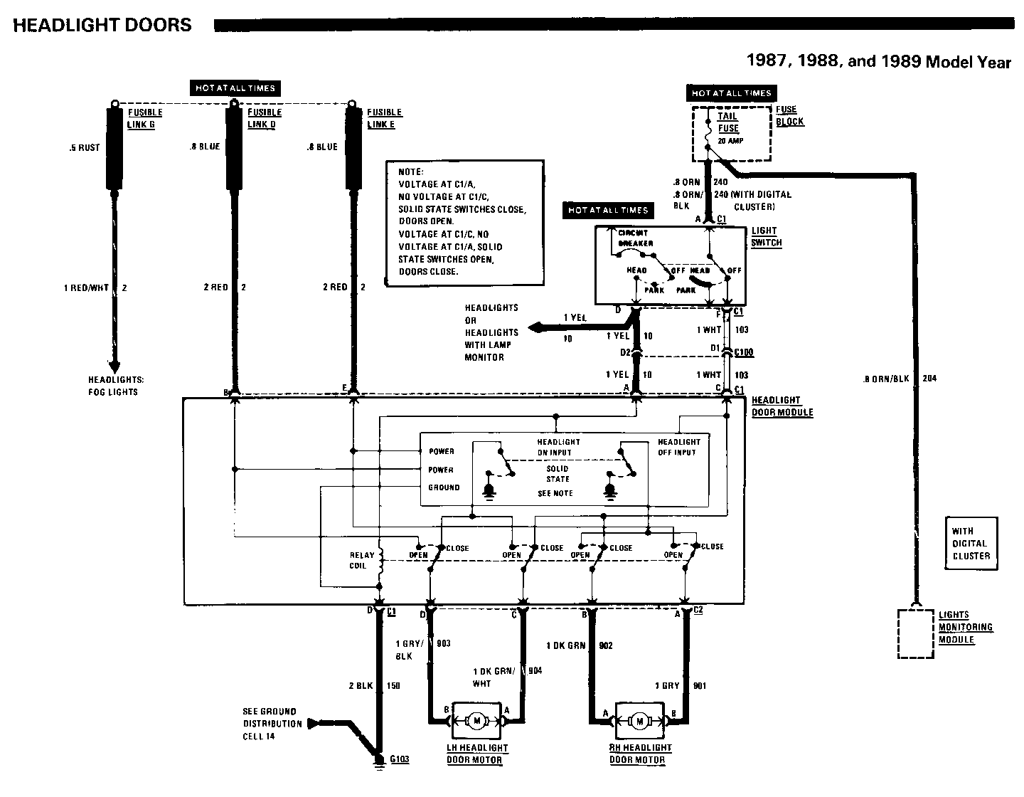
MANUAL UPDATE-SEC. 8A-102 HEADLIGHT DOORS-NEW SCHEMATIC

VEHICLES AFFECTED: 1987-91 PONTIAC FIREBIRD
Paqe 8A-102-0
The Headlight Door Module "internals" has been revised. Please insert the attached Headlight Door schematic into the appropriate Service Manual for the 1987, 1988 and 1989 Pontiac Firebird.
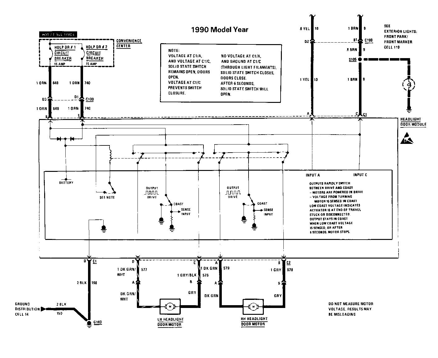
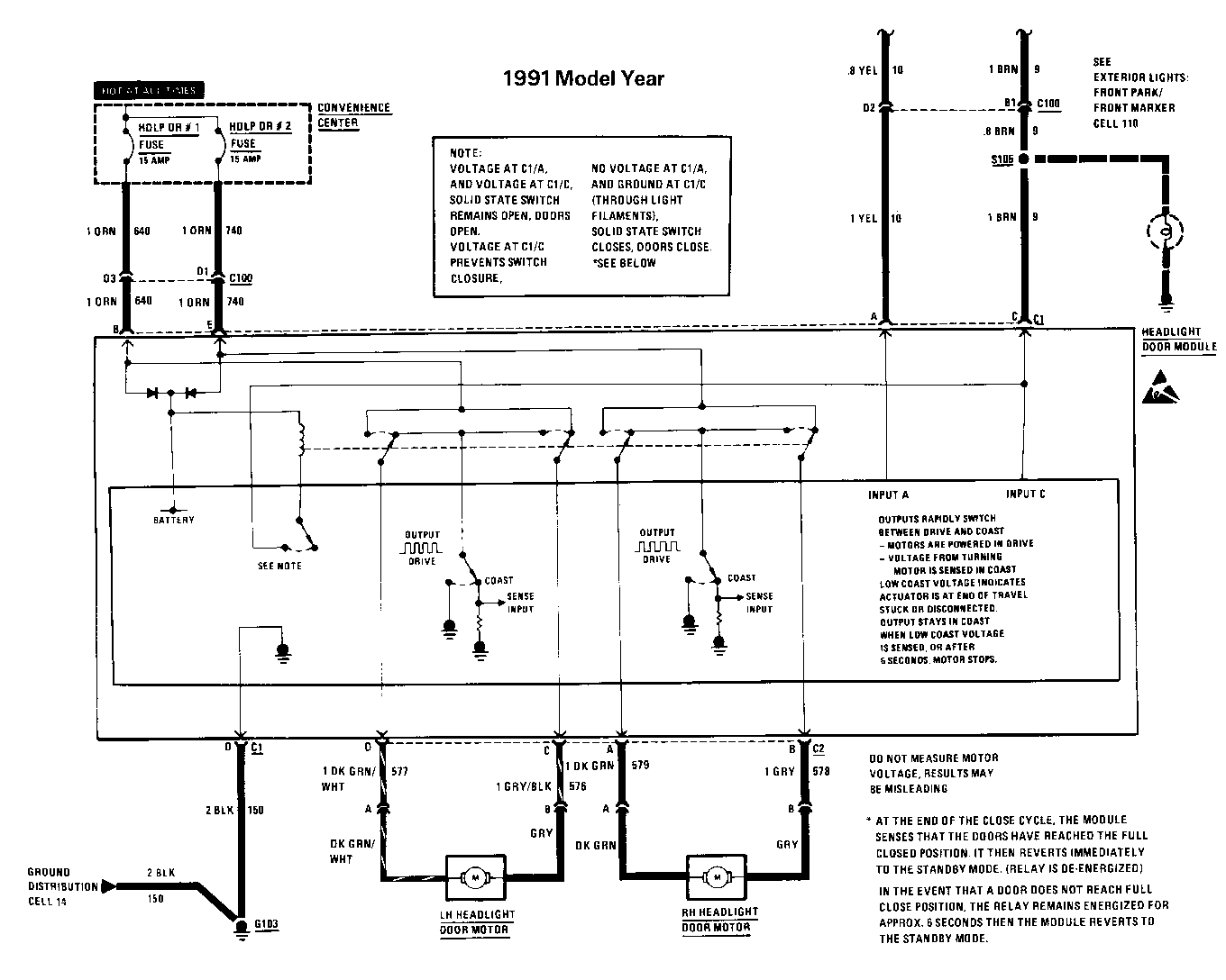
Also, the following text serves to revise the Headlight Door Motor Test and Circuit Operation text for the 1990 and 1991 Pontiac Firebird.
Page 8A-102-2 and 8A-102-3
1990 and 1991 Pontiac Firebird
HEADLIGHT DOOR MOTOR TEST
1. Disconnect connector C2 from the Headlight Door Module.
2. If the Headlight Doors are stuck in the open position, manually close Headlight Doors.
3. Using 15 amp fused jumpers, apply battery voltage to terminal C and terminal B of the Headlight Door Module connector C2. Ground terminal D and terminal A of the Headlight Door Module connector C2. Do the Headlight Doors open?
If the Headlight Doors open, go to the Headlight Door Module Test.
If a Headlight Door does not open, check the wiring to the suspect Headlight Door Motor. If OK, replace Headlight Door Motor
CIRCUIT OPERATION
Battery voltage to open and close the Headlight Doors is applied to terminals B and E of the Headlight Door Module connector Cl. The module is grounded at terminal D of connector Cl.
OPENING SEQUENCE
When the Light Switch is in Headlight or Daytime Running Lights (if so equipped) are in the night mode, battery voltage is applied to both terminals A and C of the Headlight Door Module connector C. With battery voltage applied to the Input C and Input A the Headlight Door Module's relay remains de-energized. Battery voltage remains applied to the Headlight Door Motors through terminal B and terminal C of module connector C2. The motors are controlled by the module switching the ground path. The Headlight Door Motors operate to open the Headlight Doors. When the doors are fully open the module turns off the motors.
NOTE: Measuring voltage at the motor outputs of the Headlight Door Module is NOT a valid diagnosis procedure. The module rapidly pulses the door motors on (hi) and off (low). The pulsing is too rapid to see or measure with a voltmeter. When the pulse signal is low the spinning door motor acts like a generator. The module can detect the voltage produced by the motor and continues the pulsing signal. Each door motor stops turning when its headlight door is fully open, fully closed or jammed. Once the motor stalls, no voltage is produced and the module turns off the motor. If a motor runs longer than approximately 6 seconds (disconnected drive linkage) the module will turn off the motor.
When the Light Switch is pressed OFF, battery voltage is removed from terminals A and C of connector C1 at the Headlight Door Module. The Module allows the doors to close when it sees a ground, through the many parking and instrument lights, at terminal C of connector C1. The module energizes its relay and the relay switches move to the door-close position. Battery voltage is applied to the Headlight Door Motors through terminal A and terminal D of module connector C2. The motors are controlled by the module switching the ground path. The Headlight Door Motors operate to close the Headlight Doors. When the doors are fully closed the module turns off the motors.
NOTE: Measuring voltage at the motor outputs of the Headlight Door Module is NOT a valid diagnosis procedure. See Opening Sequence for additional information.


General Motors bulletins are intended for use by professional technicians, not a "do-it-yourselfer". They are written to inform those technicians of conditions that may occur on some vehicles, or to provide information that could assist in the proper service of a vehicle. Properly trained technicians have the equipment, tools, safety instructions and know-how to do a job properly and safely. If a condition is described, do not assume that the bulletin applies to your vehicle, or that your vehicle will have that condition. See a General Motors dealer servicing your brand of General Motors vehicle for information on whether your vehicle may benefit from the information.
