UPDATE-THEFT DETERRENT SYSTEMS PASS KEY SYSTEM-SERVICE INFO.

MODELS/YEARS 1990 TORONADO MODELS
This bulletin includes the information pertaining to Service Manual Section 9D, Theft Deterrent Systems, which was not included with the 1990 "Toronado Preliminary Service Manual".
Section 9D contains General Description and Service Procedures, Section 8A-133 (which can be found in the 1990 "Toronado Preliminary Service Manual") contains PASS KEY diagnosis procedures.
SECTION 9D THEFT DETERRENT SYSTEMS TABLE OF CONTENTS
PASS KEY SYSTEM .................9D-1 SERVICE PROCEDURES............ 9D-3 GENERAL DESCRIPTION ............. 9D-1 DIAGNOSIS .................... 8A-133
PERSONAL AUTOMOTIVE SECURITY SYSTEM
GENERAL DESCRIPTION
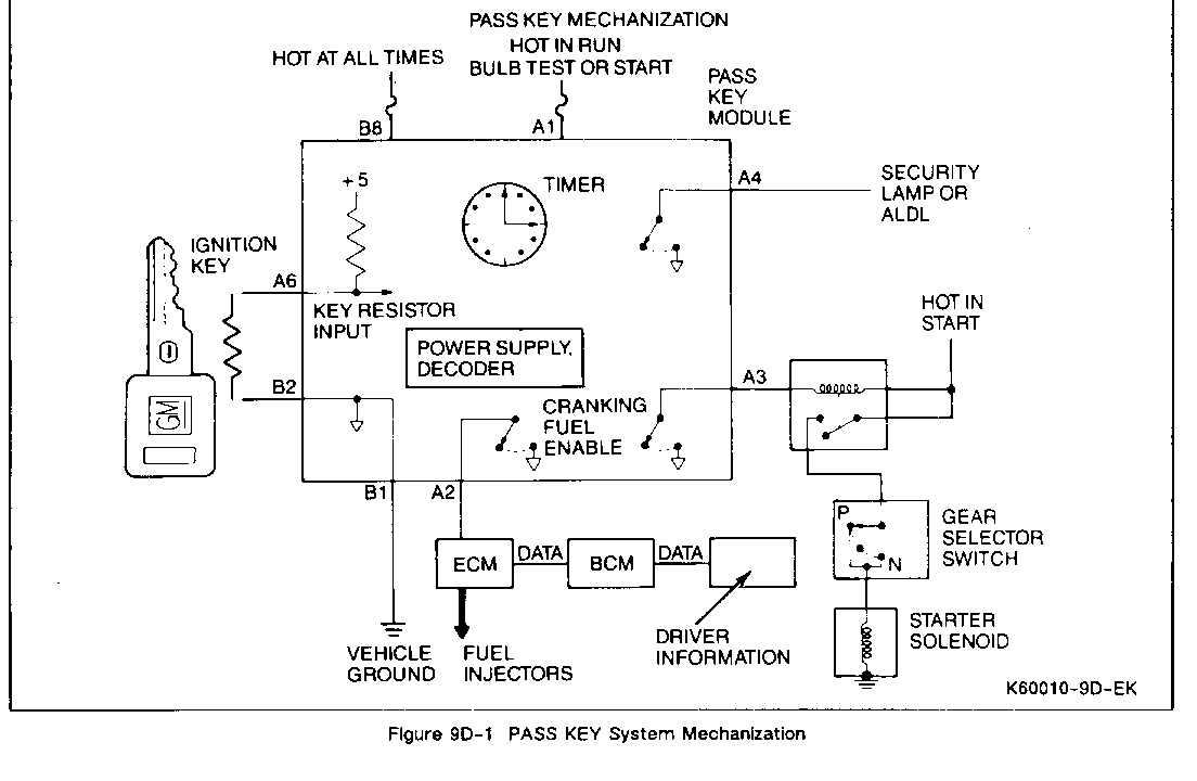
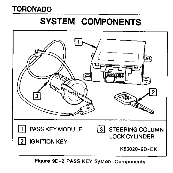
The Personal Automotive Security System (PASS KEY) is standard equipment on this vehicle. The system is designed to prevent vehicle theft by disabling the engine unless a key with a specific electrical resistance is used in the steering column. The components of the system are the Ignition Key, the Steering Column Lock Cylinder, the PASS KEY Module, the Starter Enable Relay, and the Engine Control Module (ECM). Each Component is discussed separately, below.
SYSTEM OPERATION
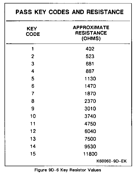
The PASS KEY system is designed to prevent the engine from starting if the proper resistance is not sensed from the Ignition Key. Of the 15 resistance values available, only one will work with each PASS KEY module.
The PASS KEY system prevents the engine from starting by controlling the Starter Enable Relay and the ECM Fuel Enable input. If the ECM does not sense the proper pulse width modulated (PWM) signal on the Fuel Enable input, it will not provide fuel to the engine.
If the wrong resistance value is sensed when the ignition is turned on, the PASS KEY Module will not ground the Starter Enable circuit and will not output the Fuel Enable PWM signal for approximately three minutes. This prevents the engine from starting and discourages the thief from trying key codes (resistance values) at random.
If the correct resistance is sensed when the ignition is turned on, the PASS KEY Module will ground the Starter Enable circuit and output the Fuel Enable PWM signal. This will allow the engine to start normally.
Ignition Key
The Ignition Key for cars equipped with PASS KEY is an assembly of a typical square ignition key blank and a resistor pellet. The key blank and resistor pellet are not serviceable separately. There are 15 different Ignition Key assemblies, each with a different resistance value. The Ignition Key also has mechanical cuts similar to non PASS KEY Ignition Keys. Steering Column Lock Cylinder
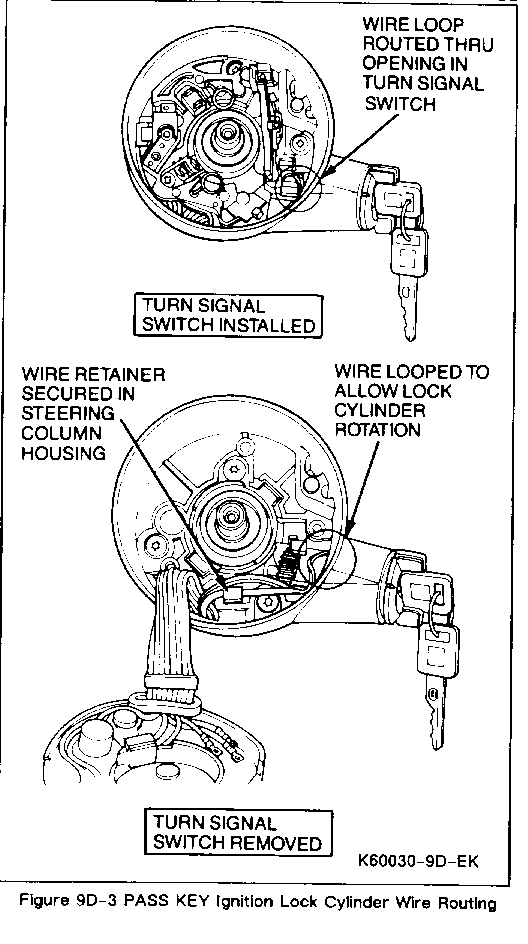
The Steering Column Lock Cylinder in cars equipped with PASS KEY contains a set of electrical contacts used to measure the resistor in the Ignition Key. The wire routing for the contacts inside the steering column is very critical. When servicing the lock cylinder set, be certain to maintain proper wire routing (Figure 9D-3). A two way connector at the base of the steering column connects the contacts to the vehicle wiring. The connector is also used for diagnostic purposes. The Steering Column Lock Cylinder also performs all functions of lock cylinders on non PASS KEY cars. When replacing a Steering Column Lock Cylinder, it will be necessary to make new keys which match the PASS KEY key code of the PASS KEY Module and the mechanical cut of the new Lock Cylinder.
PASS KEY Module
The PASS KEY Module contains the logic of the PASS KEY system. The PASS KEY Module has inputs from the Ignition circuit and the Ignition Key Resistor. The Module has outputs to the Starter Enable circuit, the Fuel Enable circuit, and the security lamp.
IGNITION INPUT
The ignition input is used to turn the Module on. When the Module is turned on, it will read the Ignition Key Resistor and control the outputs accordingly. When the Module is turned off the Ignition Key Resistor is not read and the Starter Enable Relay and Fuel Enable output will not allow the engine to start. When the Ignition is turned off, the battery input to the PASS KEY Module will draw about 1 milli-amp.
IGNITION KEY RESISTOR INPUT
The Ignition Key Resistor inputs are used to determine if the correct key is being used to start the car. The Ignition Key Resistor inputs are read only when the PASS KEY Module is first turned on. If the resistance value of the Ignition Key matches the value stored in the PASS KEY Module, then the Starter Enable Relay and Fuel Enable output will allow the vehicle to start. If the resistance value of the Ignition Key does not match the value stored in the PASS KEY Module, the Starter Enable Relay and Fuel Enable output will not allow the vehicle to start.
STARTER ENABLE OUTPUT
The Starter Enable circuit controls the Starter Enable Relay. When the PASS KEY Module sees the proper resistance at the Ignition Key, it grounds the Starter Enable circuit, which allows the engine to be cranked. If the PASS KEY Module does not see the proper resistance at the Ignition Key, it will not ground the Starter Enable circuit
FUEL ENABLE OUTPUT
The Fuel Enable circuit is an output from the PASS KEY Module and an input to the ECM. When the PASS
KEY Module sees the proper resistance at the Ignition Key, it will output a pulse width modulated (PWM) signal to the ECM. If the PASS KEY Module does not see the proper resistance at the Ignition key it will not output the PWM signal to the ECM.
SECURITY LAMP OUTPUT
The Security lamp circuit is an indicator lamp output. The output will be grounded during a two second "bulb test" at key on, at any time that the PASS KEY module is preventing the engine from starting, or if the PASS KEY module is not properly programmed. See "Security Lamp Operation" for more details.
Starter Enable Relay
The Starter Enable Relay is used to stop the engine from cranking if the correct resistance is not sensed at the Ignition Key. It prevents the engine from cranking by opening the circuit to the starter solenoid.
Engine Control Module
The ECM reads the Fuel Enable circuit to determine if fuel injection should be allowed. If the Fuel Enable PWM signal is not present, the ECM will not allow fuel injection. If the PWM signal is present, the ECM will allow fuel injection and normal engine operation.
The ECM has some diagnostic features associated with the PASS KEY Fuel Enable input. Refer to section 6E of this manual for details on ECM trouble codes.
SECURITY LAMP OPERATION
The PASS KEY system controls the "Security" indicator lamp. In normal operation, the PASS KEY module controls the lamp only when the ignition is on. The four bulb control modes for the PASS KEY system are listed below. Other modes such as blown fuses, loose ground circuits, or burned out bulbs will affect the bulb operation in other manners and should be diagnosed by referring to Section 8A-133.
Bulb Check
When the ignition is first turned on, the "Security" indicator will illuminate for approximately two seconds to indicate the system is operating correctly. Refer to the bulb symptoms below if the bulb check does not appear.
Bulb Stays Illuminated and Engine Starts
If the "Security" indicator stays illuminated after the engine starts this is an indication that the PASS KEY module is not properly programmed to accept only one key value. This will most likely occur only on a vehicle which has just had the PASS KEY module replaced. Verify that the PASS KEY module connection at the base of the steering column is properly connected and that a good ignition key is being used. Refer to the diagnosis procedures in Section 8A-133 for more diagnosis information
Bulb Stays Illuminated and Engine does not Start
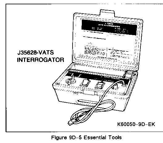
If the "Security" indicator stays illuminated while and after attemptirig to start the engine and the engine does not start this indicates that the PASS KEY module has sensed an improper key value and has disabled the engine and set the disable timer. This specifically does not mean that the key sense circuit is open or shorted to chassis ground (see next paragraph). Remove the key from the ignition and verify that it has the correct key code for the vehicle. The key code may be checked using tool J-35628 and comparing the key code to that of other keys for the vehicle. After waiting approximately 3 minutes for the disable timer to expire try to start the engine with a known good key with the proper key code. If the engine still won't start, refer to the diagnosis procedures in Section 8A-133 for more diagnosis information.
Bulb Never Illuminates and Engine does not Start
If the " Security" indicator does not illuminate at all and the engine does not start this indicates that the PASS KEY module sensed an open, a short, or otherwise invalid (value matched none of the available 15 key codes) input from the Ignition Key resistor input. During this mode of operation the PASS KEY module will not start the disable timer. This mode of operation could also be caused by malfunctioning power or ground circuits. Check that the ignition key is not damaged and refer to the diagnosis procedures in Section 8A-133 for correction.
SERVICE PROCEDURES
REPLACING THE PASS KEY MODULE
If a PASS KEY Module is bad, it should be replaced with a new PASS KEY Module. It is not necessary to match the replacement PASS KEY Module to the Ignition Key. The replacement PASS KEY Module will "learn" the Ignition Key code (resistance value) the first time it is turned on. The Ignition Key code is learned permanently, so caution should be used to ensure that unwanted key codes are not learned.
COPYING PASS KEY IGNITION KEYS
To copy a PASS KEY Ignition Key, it is necessary to first determine which key code (resistance value) is needed. The Ignition Key being copied must be tested to determine the key code. The key may be tested using an ohmeter and the table in Figure 9D-6 or by using J-35628, PASS KEY (VATS) Interrogator. To use J-35628, turn the tool on, make sure the tool wiring connectors are disconnected and insert the key into the tool lock cylinder. The "Key Code Reader" will display the key code of the Ignition Key. Obtain a key blank matching this key code and cut it to match the original key.
REPLACING LOST PASS KEY IGNITION KEYS
To replace lost PASS KEY Ignition Keys it is necessary to determine the mechanical cut and the electrical key code.
The mechanical and electrical codes are recorded on the vehicle invoice. If these codes are available, use them to create a new key. If they are not, follow the procedure below.
The mechanical cut must be determined first. The mechanical cut can be determined from the key code on the Ignition Lock Cylinder or from the original key "knock outs". If the mechanical cut cannot be determined, the Ignition Lock Cylinder should be replaced. Make a key with the correct mechanical cut to use while determining the proper electrical key code.
To determine the proper electrical key code use tool J-35628 and the following procedure:
1. Connect the tool wiring to the PASS KEY dash connector at the base of the steering column. Do not connect to the Steering Column wiring.
2. Turn J-35628 on and place key code switch to "1" and attempt to start engine with proper mechanically cut key. If engine starts, the key code is "1".
3 If engine does not start, turn ignition off and press 4 minute timer on J-35628.
4. When timer light goes out place key code switch to "2" and attempt to start egine. If engine starts, key code is "2".
5. Continue trying different key codes until proper key code is found.
Make a new key with the proper PASS KEY key code and mechanical cut.
DIAGNOSIS
Refer to Section 8A-133 for system diagnosis.
ON CAR SERVICE
R & R Steering Column Lock Cylinder
See section 3F of this manual.
R & R PASS KEY Module
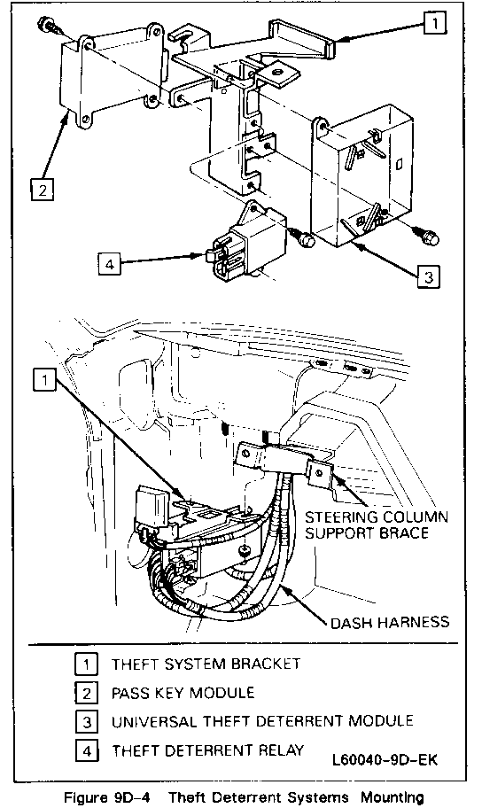
Remove or Disconnect (Figure 9D-4)
1. Left sound insulator panel.
2. Two PASS KEY bracket mounting nuts
3. PASS KEY Module from bracket
Install or Connect
1. PASS KEY Module to bracket
2. Two PASS KEY bracket mounting nuts
3. Left sound insulator panel
R & R Starter Enable Relay
Remove or Disconnect
1. Left sound insulator panel
2. Two PASS KEY bracket mounting nuts
3. Starter Enable Relay
Install or Connect
1. Starter Enable Relay
2. Two PASS KEY bracket mounting nuts
3. Left sound insulator panel
General Motors bulletins are intended for use by professional technicians, not a "do-it-yourselfer". They are written to inform those technicians of conditions that may occur on some vehicles, or to provide information that could assist in the proper service of a vehicle. Properly trained technicians have the equipment, tools, safety instructions and know-how to do a job properly and safely. If a condition is described, do not assume that the bulletin applies to your vehicle, or that your vehicle will have that condition. See a General Motors dealer servicing your brand of General Motors vehicle for information on whether your vehicle may benefit from the information.
