Tools Required
J 43094 Spark Plug Boot Puller
Removal Procedure
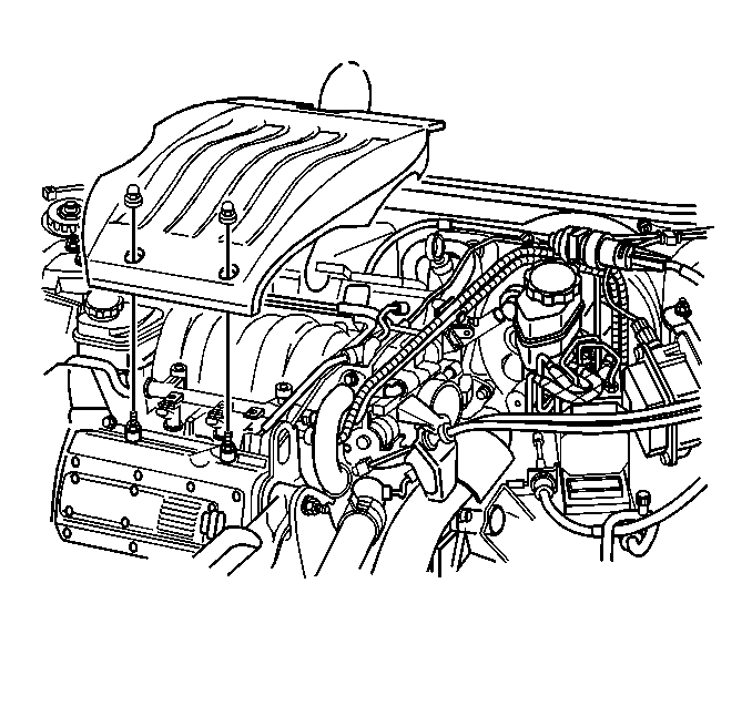
- Remove the 2 fuel injector sight shield nuts at the front of the fuel injector sight shield.
- Lift the fuel injector sight shield up at the front and slide out of the engine bracket.
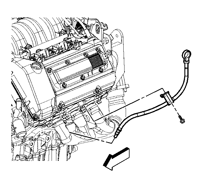
- Remove the oil tube bolt and adjust the oil tube for access.
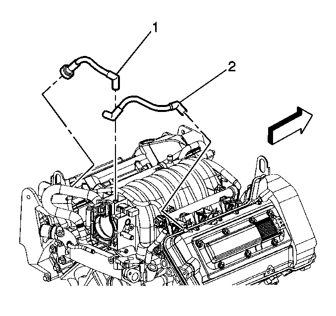
- Disconnect the PCV valve and feed tube (1) from the left (front) camshaft cover.
- Remove the left (front) ignition coil assembly from the left (front) camshaft cover. Refer to Ignition Coil Replacement in Engine Controls-3.5L.
- Remove the engine wiring harness channel bolt from the left (front) camshaft cover.
- Reposition the engine wiring harness and the channel.
- Remove the vacuum line from the left A.I.R. check valve, if equipped.
- Reposition the vacuum lines from the camshaft cover.
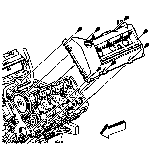
- Remove the left (front) camshaft cover retaining bolts .
- Lift the left (front) camshaft cover off the left (front) cylinder head evenly.
- Insert the J 43094 and rotate the spark plug boot prior to removing the boot. Remove the spark plug boots using the J 43094 . Inspect the spark boots. Replace as necessary.
- If necessary, disassemble the camshaft cover. Refer to Camshaft Cover Disassemble .
- Clean and inspect the camshaft cover. Refer to Camshaft Cover Cleaning and Inspection .


Important: The left (front) camshaft cover seals (perimeter and spark plug) should be reused unless they are damaged or if the perimeter seal is pulled from its groove during removal.
Installation Procedure
- If necessary, assemble the camshaft cover. Refer to Camshaft Cover Assemble .
- Wipe the left (front) cylinder head sealing surface with a clean, lint-free cloth.
- Inspect the left (front) camshaft cover seals (perimeter and spark plug) for damage. Check to make sure the perimeter seal is not pulled from its groove. Replace the seals if they are damaged or pulled from the groove.
- Place the left (front) camshaft cover in position on the cylinder head.
- Install the left (front) camshaft cover retaining bolts .
- Install the spark plug boots to the ignition coil assembly.
- Install the left (front) ignition coil assembly to the left (front) camshaft cover. Refer to Ignition Coil Replacement in Engine Controls-3.5L.
- Connect the PCV valve and feed tube (1) to the left (front) camshaft cover.
- If equipped with A.I.R., reposition the vacuum lines to the camshaft cover.
- If equipped, install the vacuum line to the left A.I.R. check valve.
- Install the engine wiring harness and channel. Refer to Engine Controls Component Views in Engine Controls-3.5L.
- Install the engine wiring harness channel bolt to the left (front) camshaft cover.
- Return the oil indicator tube to the proper position and install the oil indicator tube bolt.
- Insert the tab of the fuel injector sight shield under the engine bracket.
- Lower the fuel injector sight shield, and align the holes in the shield with the studs.
- Install the 2 fuel injector sight shield nuts onto the studs.

Notice: Use the correct fastener in the correct location. Replacement fasteners must be the correct part number for that application. Fasteners requiring replacement or fasteners requiring the use of thread locking compound or sealant are identified in the service procedure. Do not use paints, lubricants, or corrosion inhibitors on fasteners or fastener joint surfaces unless specified. These coatings affect fastener torque and joint clamping force and may damage the fastener. Use the correct tightening sequence and specifications when installing fasteners in order to avoid damage to parts and systems.
Tighten
Tighten the left (front) camshaft cover retaining bolts to 9 N·m
(80 lb in).

Tighten
Tighten the engine wiring harness channel bolts to 10 N·m
(89 lb in).
Tighten
Tighten the bolt to 9 N·m (80 lb in).

Notice: Use the correct fastener in the correct location. Replacement fasteners must be the correct part number for that application. Fasteners requiring replacement or fasteners requiring the use of thread locking compound or sealant are identified in the service procedure. Do not use paints, lubricants, or corrosion inhibitors on fasteners or fastener joint surfaces unless specified. These coatings affect fastener torque and joint clamping force and may damage the fastener. Use the correct tightening sequence and specifications when installing fasteners in order to avoid damage to parts and systems.
Tighten
Tighten the fuel injector sight shield nuts to 3 N·m (27 lb in).
