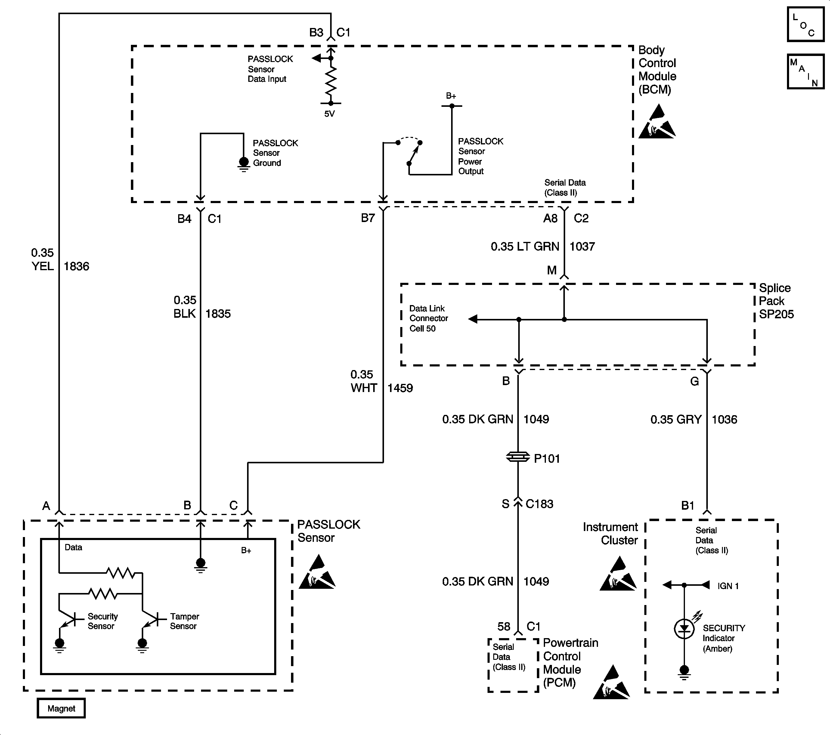
Circuit Description
The Passlock™ theft deterrent system contains a Passlock™ sensor. The Passlock™ sensor is part of the ignition lock cylinder assembly. The body control module (BCM) provides voltage (B+) to the Passlock™ sensor through circuit 1459 when the ignition switch is in the accessory, on, or start. The BCM also provides ground to the Passlock™ sensor through circuit 1835. The Passlock™ sensor interfaces with the BCM through the Passlock™ detection circuit 1836.
When turning the ignition switch to the start position with the proper key, the Passlock™ sensor generates an analog voltage signal. This signal is sent through the Passlock™ detecting circuit. This analog voltage signal is of a specific value to the vehicle, and varies from vehicle to vehicle. When attempting to start the engine, the BCM compares a preset stored analog voltage value with the signal coming from the sensor. Because both values match, the BCM sends a fuel enable password via the Class 2 serial data link to the powertrain control module (PCM). As a result, the PCM enables the crank relay, and allows fuel delivery to the engine.
When attempting to start the engine by means other than using the proper key in the ignition switch, the Passlock™ sensor sends an analog voltage signal of a different value. The BCM compares the preset stored analog voltage value with the signal coming from the sensor. Because both values do not match, the BCM sends a fuel disable password via the Class 2 serial data link to the powertrain control module (PCM). As a result, the PCM disables the crank relay, and stops fuel delivery to the engine.
When a BCM is replaced, it must be programmed to accept the analog voltage signal of the existing Passlock™ sensor (part of the ignition lock cylinder) to allow Passlock™ operation. When the BCM is replaced, the service replacement BCM is programmed to accept the first analog voltage signal it detects. If the BCM is unable to detect a valid Passlock™ analog voltage signal, the BCM will never end the programming sequence and B3031 will set.
Conditions for Setting the DTC
The BCM is unable to detect a valid analog voltage signal during programming a service replacement BCM, due to other malfunctions present (i.e. an open or short in the Passlock™ circuits).
Action Taken When the DTC Sets
| • | The BCM stores DTC B3031 in the BCM memory. |
| • | The BCM enters fail-enable mode. |
| • | The BCM sends a message to the instrument cluster to turn ON the SECURITY indicator. |
| • | The BCM sends a message to the PCM via Class 2 serial data link to enable the crank relay, and to deliver fuel to the engine; this action allows the engine to crank and start. |
Conditions for Clearing the DTC
| • | A current DTC B3031 clears when the BCM detects a valid Passlock™ sensor analog voltage signal on the Passlock™ detection circuit 1836. |
| • | A history DTC will clear after 100 consecutive ignition cycles if the condition for the malfunction is no longer present. |
| • | Using a scan tool. |
Diagnostic Aids
| • | If there is an open or short in circuits 1459, 1835, or 1836, the BCM will be unable to read a valid analog voltage signal from the Passlock™ sensor when the program mode is active. |
| • | Always diagnose the following BCM DTCs first before diagnosing this DTC. These DTCs will affect the BCM's ability to properly read a Passlock™ analog voltage signal: |
| - | B2947 |
| - | B2957 |
| - | B2958 |
| - | B3033 |
| • | If DTC B3031 is set in the BCM as a history DTC, clear the DTC and recheck the system. A history DTC B3031 indicates that the BCM has successfully completed the programming mode. |
| • | Check for poor connections at both the BCM and the ignition lock cylinder assembly, these could cause an open, incorrect Passlock™ sensor voltage signal, or intermittent malfunction. If the DTC is a history DTC, the problem may be intermittent. Try performing the tests shown while moving wiring, connectors, and the key, this can often cause the malfunction to appear. |
Test Description
The number(s) below refer to the step number(s) on the diagnostic table.
-
Checks if the BCM has successfully completed the programming mode.
-
Checks for a circuit malfunction between the BCM and the Passlock™ sensor, not allowing the BCM to complete the programming mode.
Step | Action | Value(s) | Yes | No | ||||||||
|---|---|---|---|---|---|---|---|---|---|---|---|---|
1 | Was the BCM Diagnostic System Check performed? | -- | ||||||||||
Does this DTC reset as a current DTC? | -- | |||||||||||
Using scan tool, check for these DTCs:
Are any of these DTCs listed above set as current DTCs in the BCM? | -- | |||||||||||
4 |
Is the repair complete? | -- | -- | |||||||||
5 |
Are there any current BCM DTCs present? | -- | System OK |
