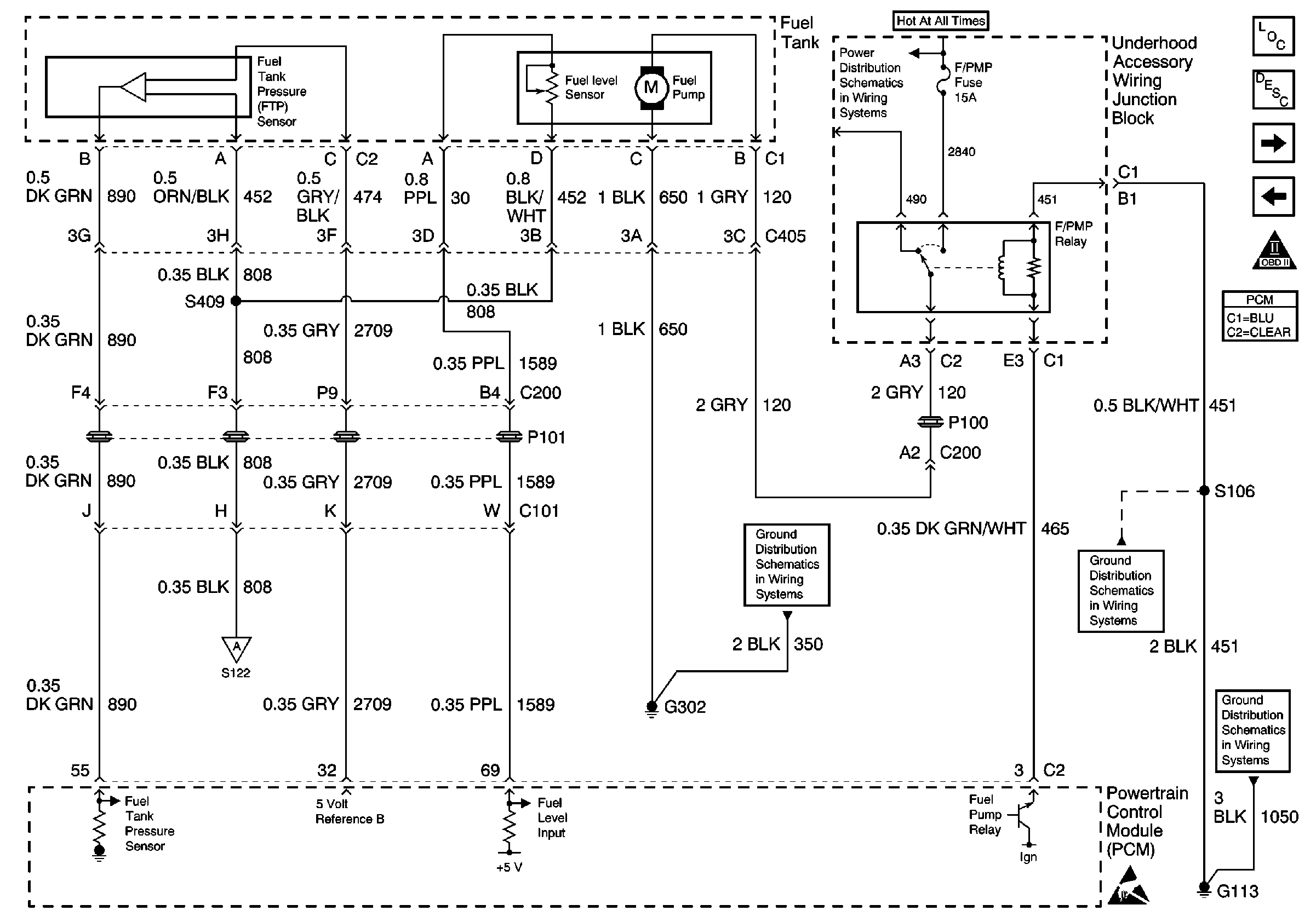
Refer to Engine Control Schematics
PCM Fuel Tank Inputs

.
Circuit Description
The powertrain control module (PCM) requires an accurate indication of the fuel level for the EVAP system diagnosis. The fuel level in the fuel tank changes the rate of vacuum decay for the EVAP system leak DTCs.
The fuel level sensor changes resistance based on fuel level. The fuel level sensor has a signal circuit and a ground circuit. The PCM applies a voltage of about 5 volts on the signal circuit to the sensor. The PCM monitors changes in this voltage caused by changes in the resistance of the sensor to determine the fuel level.
When the fuel tank is full, the sensor resistance is high, and the signal voltage is only pulled down a small amount through the sensor to ground. Therefore, the PCM will sense a high signal voltage. When the fuel tank is empty, the sensor resistance is low, and the signal voltage is pulled down a larger amount. This causes the PCM to sense a low signal voltage. The fuel level data is also sent to the instrument panel cluster (IPC) via the Serial Data line.
The normal resistance values of the sensor are as follows:
| • | 40 ohms plus or minus 2.5 ohms = Full |
| • | 248.5 ohms plus or minus 3.3 ohms = Empty |
This diagnostic table requires the following special tools:
J 33431-C Signal Generator/Instrument Panel Tester
Diagnostic Aids
Important: The fuel level is used to in EVAP system diagnosis. Always diagnose the fuel level sensor before any other EVAP system components or DTCs.
Test Description
The numbers below refer to the step numbers on the diagnostic table.
-
At 40 ohms the scan tool should display a fuel level close to 0 percent. At 248 ohms the display should be close to 100 percent. As the resistance is increased, there should be a corresponding fuel level increase. If any spikes, dips, or erratic readings occur, or if the low and high resistance values do not correspond closely to 0 percent and 100 percent, the related circuitry should be checked before replacing the sensor.
-
Before replacing the sensor, check for the possibility of foreign material in the fuel tank that may inhibit the correct float arm movement, including ice. Check for the float arm contacting other components on the fuel pump and sender assembly.
Step | Action | Value(s) | Yes | No | ||||||||
|---|---|---|---|---|---|---|---|---|---|---|---|---|
1 | Did you perform the Powertrain On-Board Diagnostic (OBD) System Check? | -- | ||||||||||
2 | Is DTC P0462, P0463, or any IPC DTC set? | -- | Go to the applicable DTC tables | |||||||||
Does the fuel level increase steadily through the specified range, from 0 percent to 100 percent? | 40 ohms 248 ohms | |||||||||||
4 |
Does the fuel gauge increase steadily throughout the specified range, from Empty to Full? | 40 ohms 248 ohms | Go to Diagnostic System Check - Instrument Cluster in Instrument Panel, Gauges, and Console | |||||||||
5 |
Was a problem found and corrected? | -- | System OK | |||||||||
6 | Check for poor connections or terminal tension at the fuel level sensor. Refer to Intermittents and Poor Connections Diagnosis in Wiring Systems . Was a problem found and corrected? | -- | System OK | |||||||||
Replace the fuel level sensor. Refer to Fuel Sender Assembly Replacement . Is the action complete? | -- | System OK | -- | |||||||||
8 |
Important: The replacement PCM must be programmed. Replace the PCM. Refer to Powertrain Control Module Replacement/Programming . Is the action complete? | -- | System OK | -- |
