SERVICE MANUAL UPDATE-SEC.6E3 REVISED CODE 26 CHARTS

MODELS/YEARS 1990 CUTLASS CALAIS, CUTLASS CIERA
This bulletin serves to update the Code 26 charts and facing pages in Section 6E3-A "Driveability And Emissions" for 1990 Cutlass Ciera and Cutlass Calais models with the 3300 (VIN N) engine. The diagnostic procedures for vehicles equipped with a 3T40 (125C) or a 4T60 (440T4) transaxle are the same except for the 2nd gear switch, which is applicable to the 3T40 (125C) transaxle only. Changes have been highlighted with shading.
Revised pages are listed below:
Page 6E3-A-42 - Code 26 (i of 3) facing page Page 6E3-A-43 - Code 26 (1 of 3) chart Page 6E3-A-44 - Code 26 (2 of 3) facing page Page 6E3-A-45 - Code 26 (2 of 3) chart Page 6E3-A-46 - Code 26 (3 of 3) facing page Page 6E3-A-47 - Code 26 (3 of 3) chart
Please mark a reference to this bulletin on each page in your copies of the affected service manual.
CODE 26 (Page 1 of 3) QUAD-DRIVER (QDM) CIRCUIT 3300 (VIN N) "A" CARLINE (PORT)
Circuit Description:
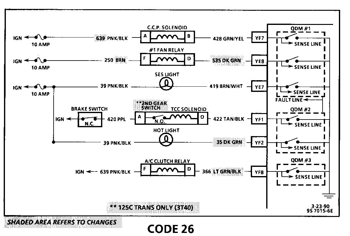
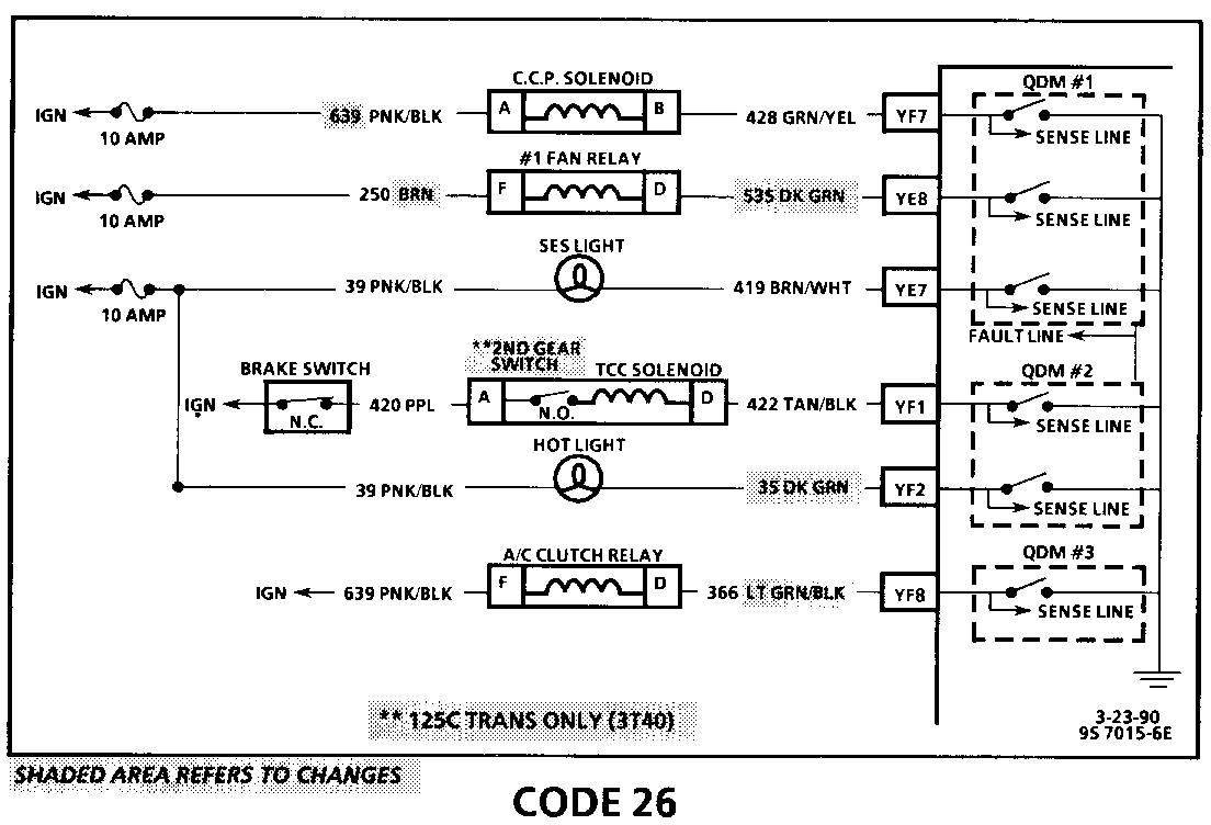
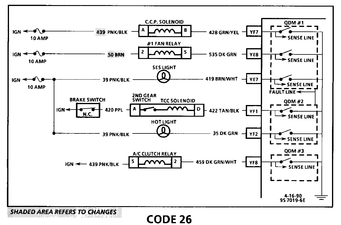
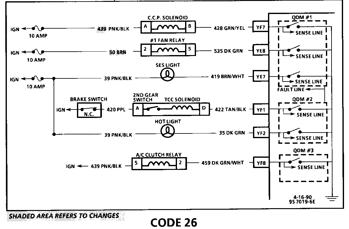
Quad-Driver Modules (QDM) are used to control the components shown in the illustration above. When the ECM is commanding a component "ON," the QDM closes the switch completing the circuit to ground.
Each QDM has a sense line and a fault line. When a component is commanded "ON," the voltage potential on the sense line is low, and when the component is commanded "OFF" the voltage potential on the sense line is high.
Code 26 will set when the ECM is commanding a component "ON" and the voltage potential on the sense line is high, or if the component is commanded "OFF" and the voltage potential on the sense line is low. QDM number 3 will not set a Code 26.
On vehicles with a 125C transaxle, the QDM status on the "Scan" tool will read HI until the second gear switch is closed. To simulate driving in second gear and change the QDM status to low, disconnect TCC connector and using a test lightjumper terminals "A" and "D" together.
Test Description: Numbers below refer to circled numbers on the diagnostic chart.
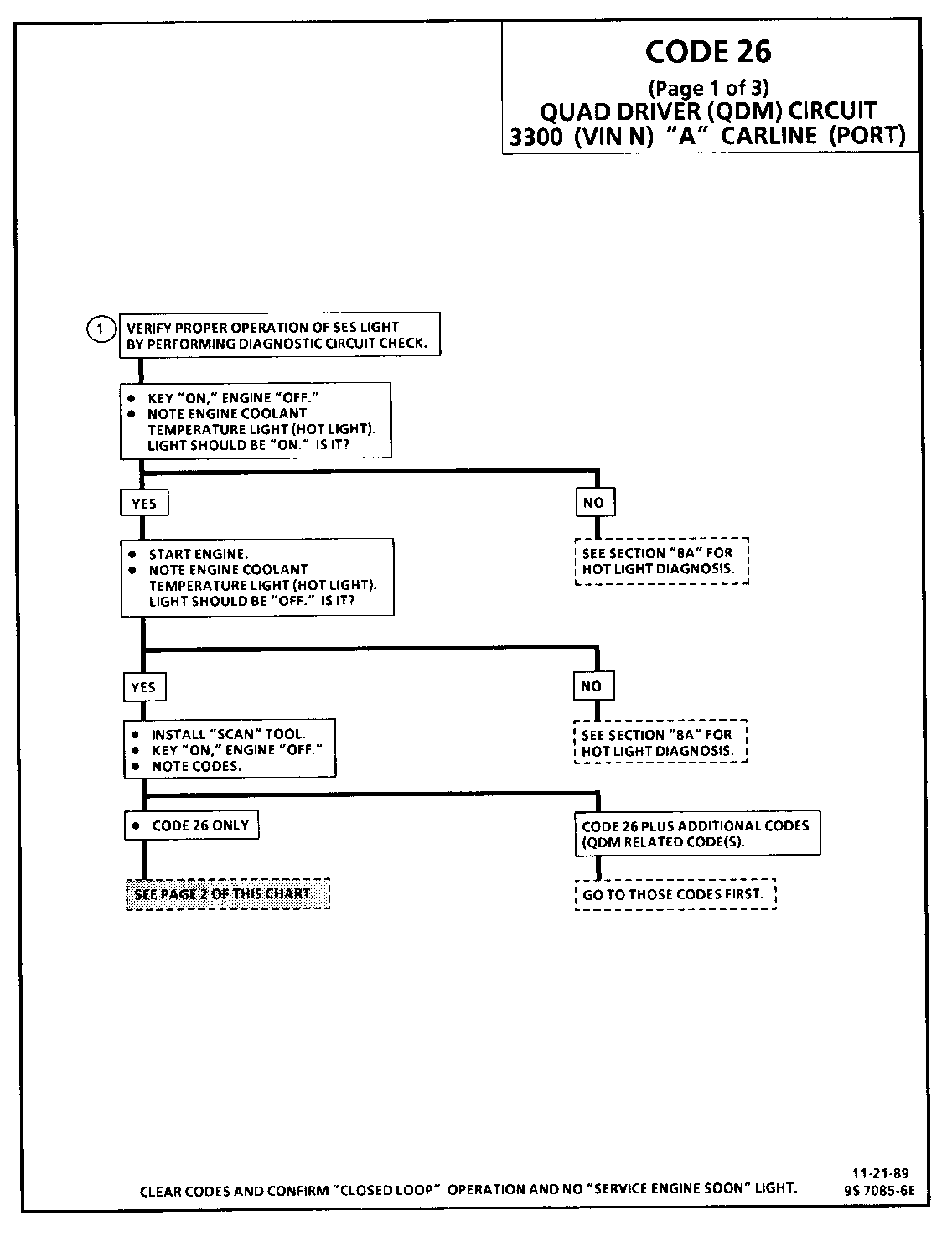
1. The ECM does not know which controlled circuit caused the Code 26 so this chart will go through each of the circuits to determine which is at fault. This test checks the "Service Engine Soon" light driver and the "Service Engine Soon" light circuit.
QDM symptoms:
- TCC - Inoperative - Code 39.
- Hot Light - "ON" all the time/"OFF" during bulb check.
- Coolant fan "ON" all the time or won't come "ON" at all, see "Electric Cooling Fan," Section "6E3-C12".
- Poor driveability due to 100% canister purge.
CODE 26 (Page 2 of 3) QUAD-DRIVER (QDM) CIRCUIT 3300 (VIN N) -A- CARLINE (PORT)
Circuit Description:
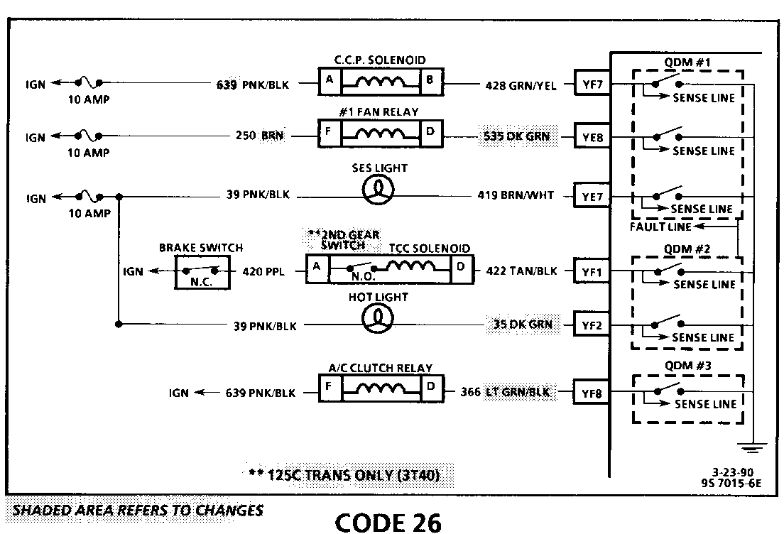
Quad-Driver Modules (QDM) are used to control the components shown in the illustration above. When the ECM is commanding a component "ON," the QDM closes the switch completing the circuit to ground.
Each QDM has a sense line and a fault line. When a component is commanded "ON" the voltage potential on the sense line is low and when the component is commanded "OFF" the voltage potential on the sense line is high.
Code 26 will set when the ECM is commanding a component "ON" and the voltage potential on the sense line is high, or if the component is commanded "OFF" and the voltage potential on the sense line is low. QDM number 3 will not set a Code 26.
On vehicles with a 125C transaxle, the QDM status on the "Scan" tool will read HI until the second gear switch is closed. To simulate driving in second gear and change the QDM status to low, disconnect TCC connector and using a test lightjumper terminals "A" and "D" together.
Test Description: Numbers below refer to circled numbers on the diagnostic chart.
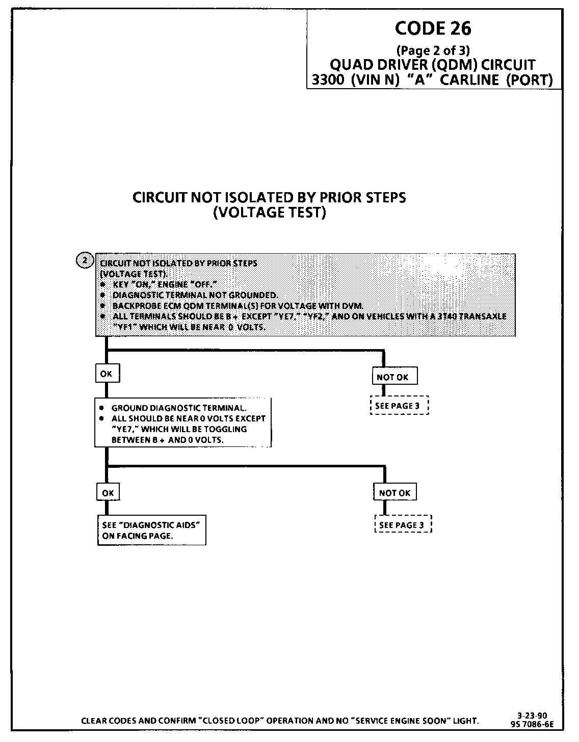
2. This test will determine which circuit isout of specifications. All circuits should be B+ when key is "ON", engine not running, EXCEPT "YE7" the SES light, and 'YF2" the "hot light," and on vehicles with the 3T40 transaxle "YF1" will also be near 0 volts. The diagnostic test terminal is not grounded.
Diagnostic Aids:
Monitor the voltage at each terminal while moving related harness connectors, including ECM harness. If the failure is induced, the voltage will change. Thismayhelplocatetheintermittent. Check for bent pins at ECM and ECM connector terminals. If code re-occurs with no apparent connector problem, replace ECM.
Code 26 (Page 3 of 3) QUAD-DRIVER (QDM) CIRCUIT 3300 (VIN N) "A- CARLINE (PORT)
Circuit Description:
Quad-Driver Modules (QDM) are used to control the components shown in the illustration above. When the ECM is commanding a component "ON," the QDM closes the switch completing the circuit to ground.
Each QDM has a sense line and a fault line. When a component is commanded "ON," the voltage potential on the sense line is low and when the component is commanded "OFF" the voltage potential on the sense line is high.
Code 26 will set when the ECM is commanding a component "ON" and the voltage potential on the sense line is high, or if the component is commanded "OFF" and the voltage potential on the sense line is low. QDM number 3 will not set a Code 26.
On vehicles with a 125C transaxle, the QDM status on the "Scan" tool will read HI until the second gear switch is closed. To simulate driving in second gear and change the QDM status to low, disconnect TCC connector and using a test lightjumper terminals "A" and "D" together.
Test Description: Numbers below refer to circled numbers on the diagnostic chart.
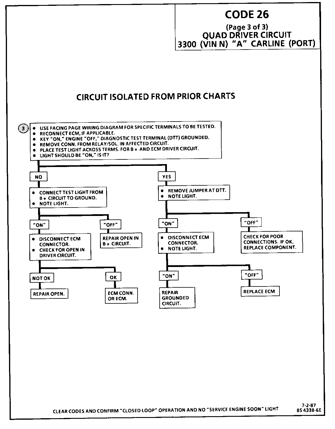
3. This test will determine if the problem is the circuit or the component. As the factory installed ECM is protected with an internal fuse, it is highly unlikely that the ECM needs to be replaced.
CODE 26 (Page 1 of 3) QUAD-DRIVER (QDM) CIRCUIT 3300 (VIN N) -N- CARLINE (PORT)
Circuit Description:
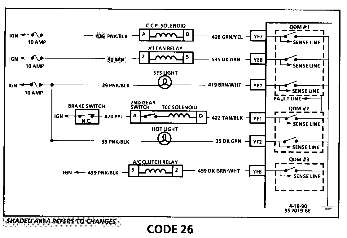
Quad-Driver Modules (QDM) are used to control the components shown in the illustration above. When the ECM is commanding a component "ON," the QDM closes the switch completing the circuit to ground.
Each QDM has a sense line and a fault line. When a component is commanded "ON," the voltage potential on the sense line is low and when the component is commanded "OFF," the voltage potential on the sense line is high.
Code 26 will set when the ECM is commanding a component "ON" and the voltage potential on the sense line is high, or if the component is commanded "OFF" and the voltage potential on the sense line is low. QDM number 3 will not set a Code 26.
Vehicles with a 125C transaxle will read "HI" until the second gear switch is closed. To check, disconnect TCC connector and using a test lightjumper terminals "A" and "D" together.
Test Description: Numbers below refer to circled numbers on the diagnostic chart.
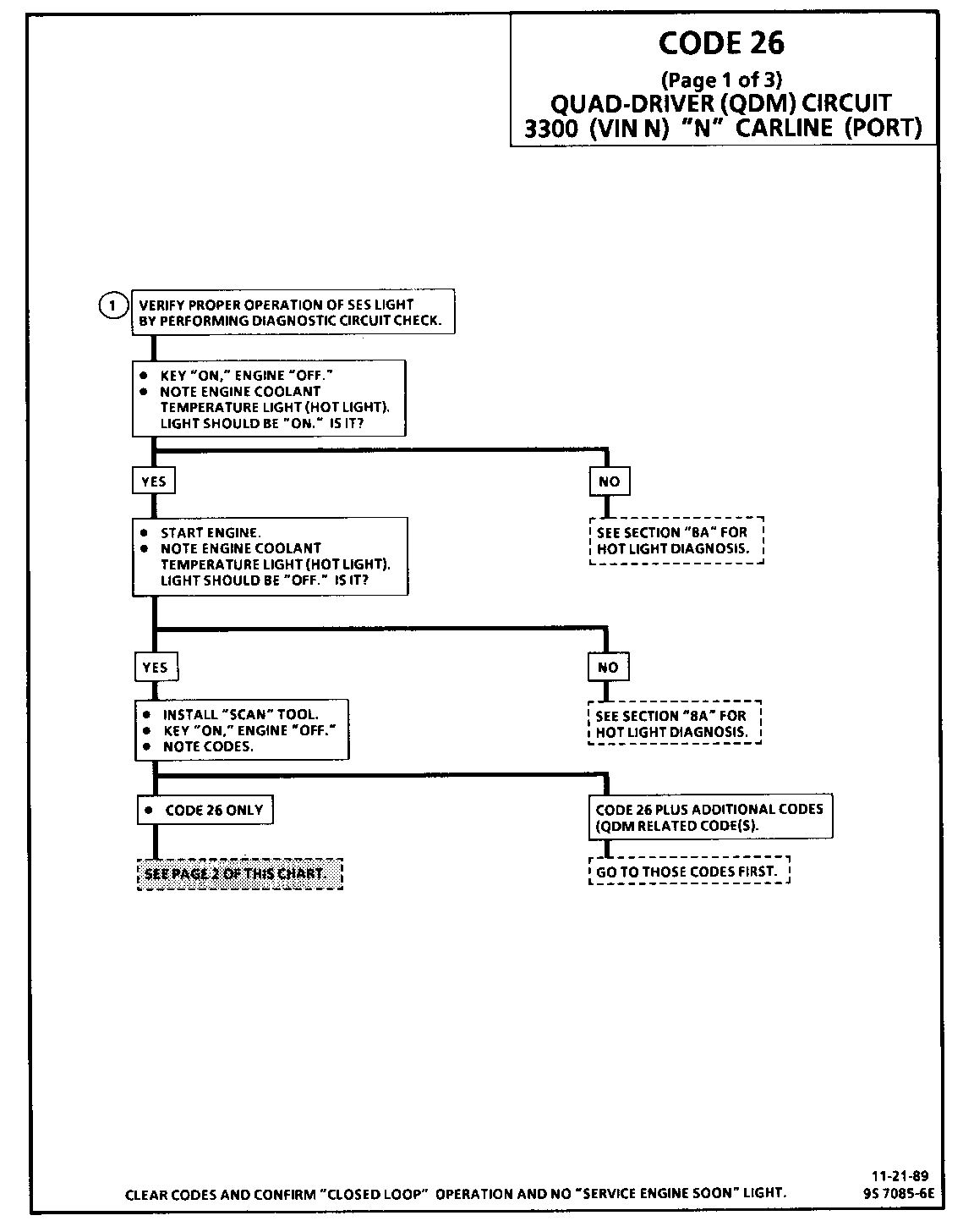
1. The ECM does not know which controlled circuit caused the Code 26 so this chart will go through each of the circuits to determine which is at fault. This test checks the "Service Engine Soon" light driver and the "Service Engine Soon" light circuit.
QDM symptoms:
- TCC - Inoperative - Code 39. - Hot Light - "ON" all the time/"OFF" during bulb check. - Coolant fan on low speed all the time or won't come "ON" at all (6E3-C12). - Poor driveability due to 1 00% canister purge.
Code 26 (Page 2 of 3) QUAD-DRIVER (QDM) CIRCUIT 3300 (VIN N) -N- CARLINE (PORT)
Circuit Description:
Quad-Driver Modules (QDM) are used to control the components shown in the illustration above. When the ECM is commanding a component "ON," the QDM closes the switch completing the circuit to ground.
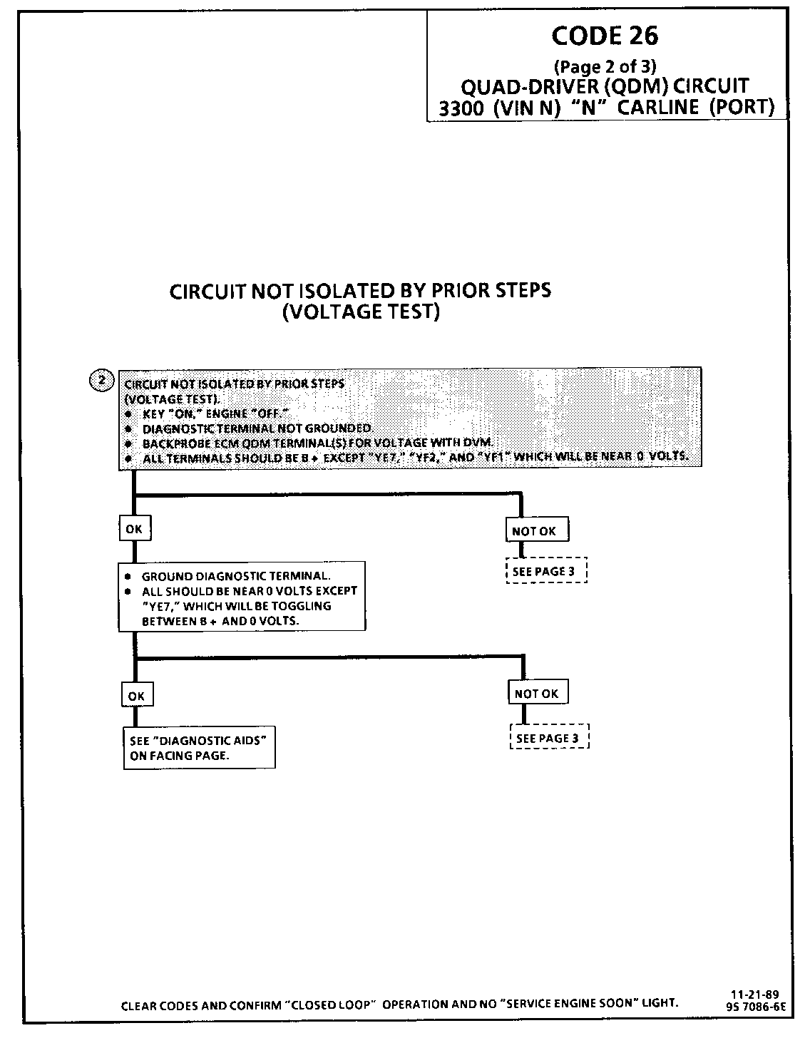
Each QDM has a sense line and a fault line. When a component is commanded "ON," the voltage potential on the sense line is low and when the component is commanded "OFF," the voltage potential on the sense line is high.
Code 26 will set when the ECM is commanding a component "ON" and the voltage potential on the sense line is high, or if the component is commanded "OFF" and the voltage potential on the sense line is low. QDM number 3 will not set a Code 26.
Vehicles with a 125C transaxle will read "HI" until the second gear switch is closed. To check, disconnect TCC connector and using a test lightjumper terminals "A" and "D" together.
Test Description: Numbers below refer to circled numbers on the diagnostic chart.
2. This test will determine which circuit is out of specificaitons. All circuits EXCEPT "YE7", the SES light, "YF1", the TCC solenoid and "YF2", the "hot light" should be B+ when key is "ON", engine not running. The diagnostic test terminal is not grounded.
Diagnostic Aids:
Monitor the voltage at each terminal while moving related harness connectors, including ECM harness. If the failure is induced, the voltage will change. Thismayhelplocatetheintermittent. Check for bent pins at ECM and ECM connector terminals. If code re-occurs with no apparent connector problem, replace ECM.
CODE 26 (Page 3 of 3) QUAD-DRIVER (QDM) CIRCUIT 3300 (VIN N) "N" CARLINE (PORT)
Circuit Description:
Quad-Driver Modules (QDM) are used to control the components shown in the illustration above. When the ECM is commanding a component "ON," the QDM closes the switch completing the circuit to ground.
Each QDM has a sense line and a fault line. When a component is commanded "ON," the voltage potential on the sense line is low and when the component is commanded "OFF," the voltage potential on the sense line is high.
Code 26 will set when the ECM is commanding a component "ON" and the voltage potential on the sense line is high, or if the component is commanded "OFF" and the voltage potential on the sense line is low. QDM number 3 will not set a Code 26.
Vehicles with a 125C transaxle will read "HI" until the second gear switch is closed. To check, disconnect TCC connector and using a test lightjumper terminals "A" and "D" together.
Test Description: Numbers below refer to circled numbers on the diagnostic chart.
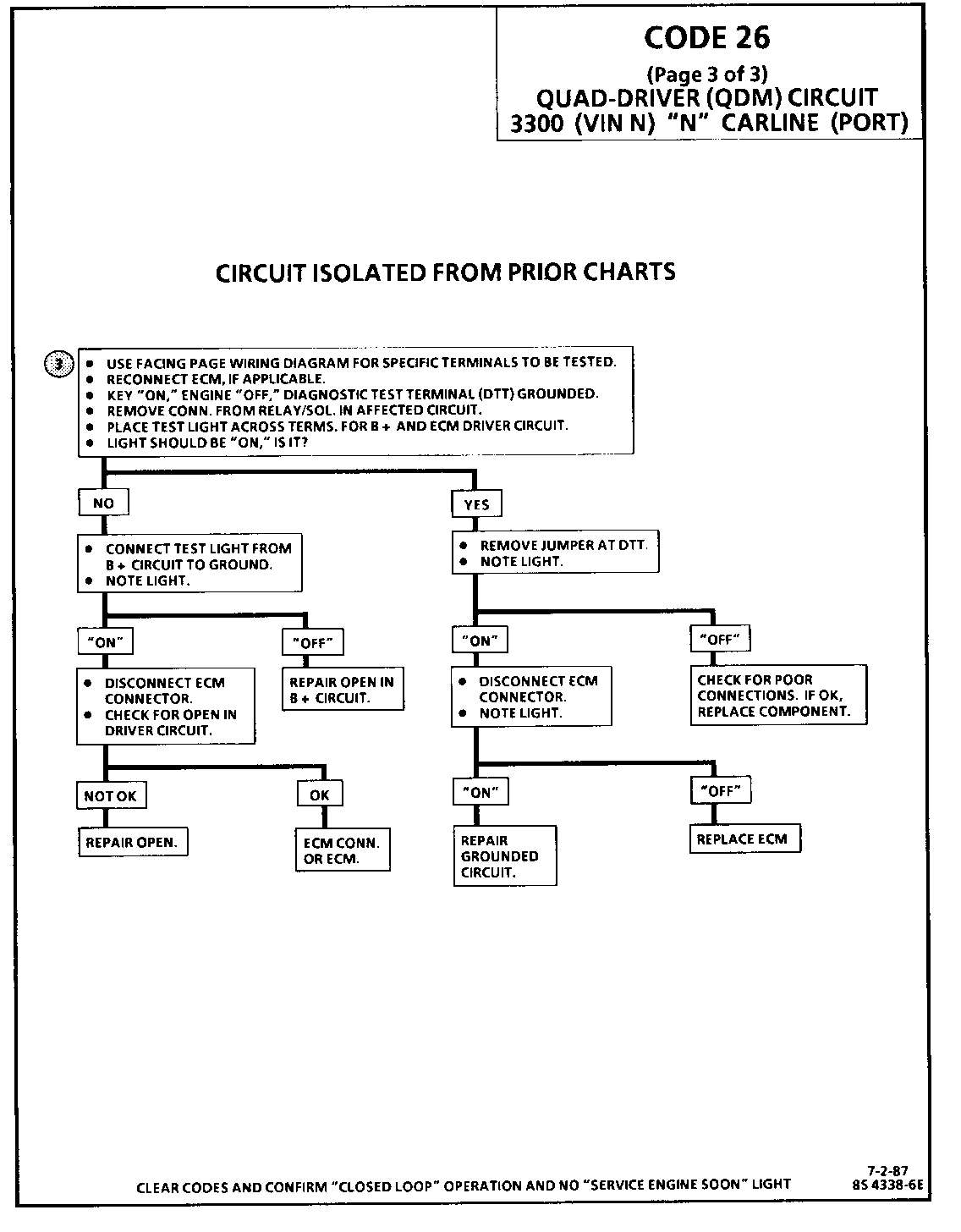
3. This test will determine if the problem is the circuit or the component. As the factory installed ECM is protected with an internal fuse, it is highly unlikely that the ECM needs to be replaced.
General Motors bulletins are intended for use by professional technicians, not a "do-it-yourselfer". They are written to inform those technicians of conditions that may occur on some vehicles, or to provide information that could assist in the proper service of a vehicle. Properly trained technicians have the equipment, tools, safety instructions and know-how to do a job properly and safely. If a condition is described, do not assume that the bulletin applies to your vehicle, or that your vehicle will have that condition. See a General Motors dealer servicing your brand of General Motors vehicle for information on whether your vehicle may benefit from the information.
