SERVICE MANUAL UPDATE SEC. 6A NEW CRANKSHAFT BALANCER TOOL

SUBJECT: S.M. UPDATE - SECTION 6A UPDATED CRANKSHAFT BALANCER REMOVAL TOOL
VEHICLES AFFECTED: 1991 "A" AND "N" CAR W/3.3L (VIN N) ENGINE
Service Information:
The procedure that follows replaces the one on page 6A6-22 of the 1991 Service Manual.
Tools Required:
J 37096 Flywheel Holding Tool J 38197 Crankshaft Balancer Puller J 36660 Torque Angle Meter
Remove or Disconnect
1. Negative battery cable.
2. Raise vehicle and suitably support. Refer to Section OA.
3. Right front wheel and tire assembly.
4. Inner fender splash shield (right side).
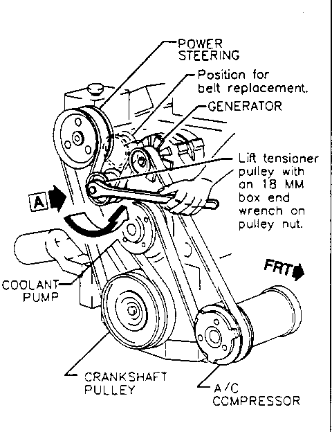
5. Accessory drive belt. Refer to Figure
6. Torque converter cover.
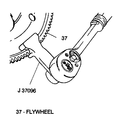
7. Hold flywheel with J 37096. Refer to Figure 2.
8. Balancer bolt.
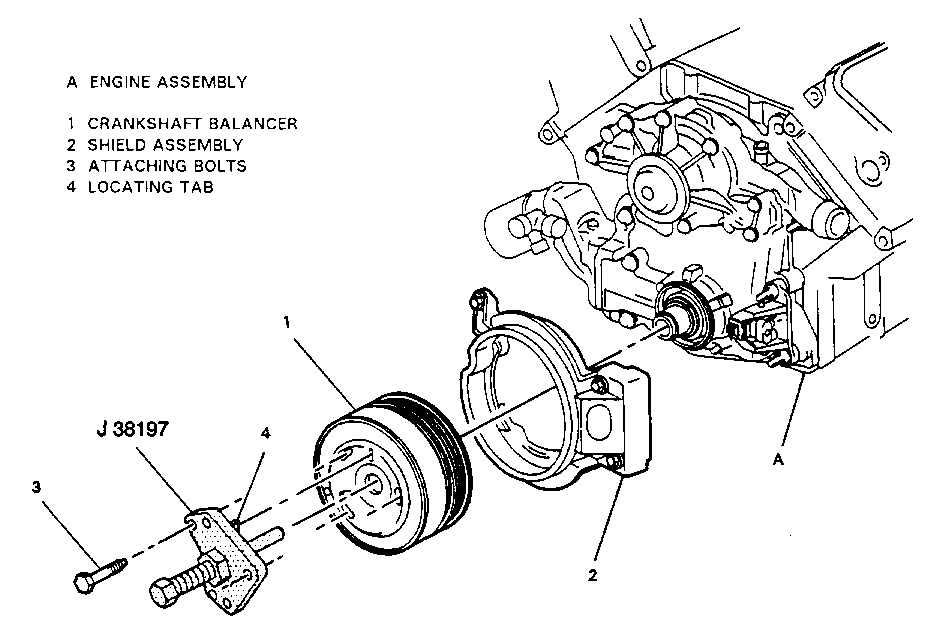
9. Crankshaft balancer using J 38197. Refer to Figure 3.
IMPORTANT
The balancer is serviced as an assembly. Do not attempt to separate pulley from the balancer hub.
Install or Connect
1. Crankshaft balancer. - Lubricate seal surface with engine oil.
2. Balancer bolt. - Hold flywheel with J 37096. Refer to Figure 2 Tighten - Balancer bolt to 150 N.m (110 ft.lbs.), then rotate 76 degrees using J 36660.
3. Inner fender splash shield.
4. Right front wheel and tire assembly.
5. Torque converter cover.
6. Lower vehicle.
7. Accessory drive belt. Refer to Figure 1.
8. Negative battery cable.


General Motors bulletins are intended for use by professional technicians, not a "do-it-yourselfer". They are written to inform those technicians of conditions that may occur on some vehicles, or to provide information that could assist in the proper service of a vehicle. Properly trained technicians have the equipment, tools, safety instructions and know-how to do a job properly and safely. If a condition is described, do not assume that the bulletin applies to your vehicle, or that your vehicle will have that condition. See a General Motors dealer servicing your brand of General Motors vehicle for information on whether your vehicle may benefit from the information.
