FRONT AXLE INNER C/V BOOT CONTACTS FRONT SHOCK

Subject: AXLE INNER C/V BOOT CONTACTS FRONT SHOCK INSPECT SHOCKS/AXLE, INSTALL SMALLER PROFILE BOOT
Model and Year: 1991 BRAVADA
Some 1991 Bravadas may exhibit a condition of the front axle tripot seals (commonly referred to as the inner C/V boots) contacting the front shock absorbers. This contact usually occurs during suspension operation and may be evidenced as torn seals, premature wear on the outer edges of the seal convolutes or grooves worn into the body of the shock absorber.
This condition can be relieved by correcting problems with shock absorber or axle installation and installing smaller profile tripot seals.
SERVICE PROCEDURE:
The following items should be checked and verified to provide the greatest amount of clearance for the tripot seals.
- The shock absorbers are installed correctly with the fluid reservoir on the bottom and the shield on the top.
- If aftermarket shock absorbers have been installed, their diameter must measure 50.4 mm (1.98") or less.
- The output shaft retaining ring is in place. To check, pull outward on the output shaft. Outward movement should measure 5 mm (.200") or less.
IMPORTANT- DO NOT cut or relocate shock absorber mounting brackets.
If the contact between the tripot joint and shock absorber is occurring on the passenger side of the vehicle, the axle assembly may be shifted in the frame too far toward the passenger side. To correct this condition the procedure below should be followed:
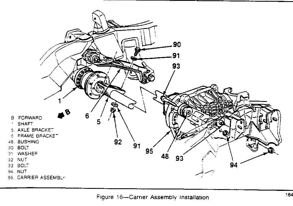
Figure 16
1. Loosen bolts (90) attaching the axle tube bracket (5) to the frame bracket (6).
2. Tighten nuts (94) to 75 N.m (55 lbs. ft.). This should cause the axle assembly to move toward the driver's side approximately 1/8" to 1/4". If the axle does not move it may be pried toward the driver's side with a bar. Position bar against the frame and the end of the shaft (1).
3. Tighten bolts (90) to 75 N.m (55 lbs. ft.).
SEAL REPLACEMENT:
After checking the shock absorber installation and front axle location, smaller profile tripot seals may be installed. These smaller seals can be identified by their visibly smaller profile and by the number 26027961 which is molded onto the seal.
Required Tools:
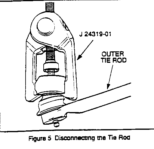
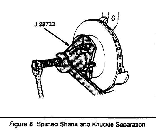
J 28733 Axle Remover J 24319-01 Tie Rod Puller J 8059 Snap Ring Pliers J 35910 Seal Clamp Tool J 34026 Ball Joint Separator
Drive Axle Removal:
1. Raise vehicle and support it with suitable safety stands.
2. Remove the wheel and tire assembly.
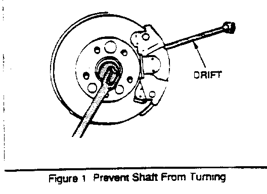
3. Insert a drift or large screwdriver through brake caliper into one of the brake rotor vanes to prevent drive axle from turning (Figure 1).
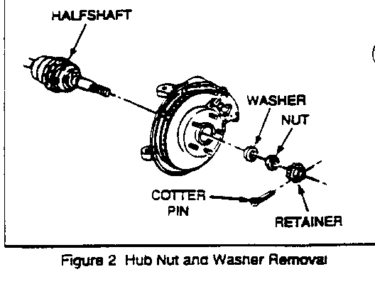
4. Remove halfshaft cotter pin, retainer, nut, and washer (Figure 2).
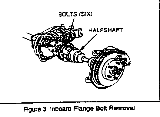
5. Loosen (do not remove at this time) six bolts securing inboard C/V joint drive flange to output shaft companion flange (Figure 3).
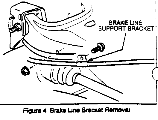
6. Remove brake line support bracket from upper control arm to allow extra travel of knuckle (Figure 4).
7. Remove cotter pin and nut from the outer tie rod.
8. Separate the outer tie rod ball stud from the steering knuckle using J24319-01 (Figure 5).
Notice: Do not attempt to disengage the joint by driving a wedge-type tool between the joint and the knuckle because the seal may be damaged.
9. Push linkage to opposite side of the vehicle and secure outer tie rod up and out of the way. This will provide the needed clearance to remove the halfshaft.
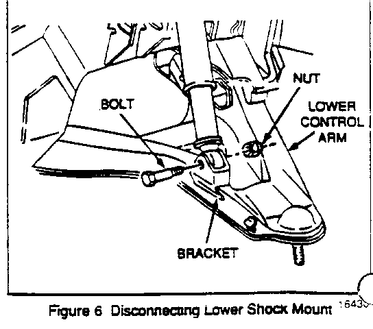
10. Remove the lower shock mounting nut and bolt (Figure 6).
11. Collapse the shock absorber.
12. Move the shock absorber up, away, and secure.
13. Depending on the type of hoist, it may be required to position floor stand between the spring seats and the lower control arm ball joint for maximum leverage. The weight of the vehicle is used to relieve the spring tension on the upper control arm.
CAUTION:
The floor jack or stand must remain under the control arm spring seat while servicing the halfshaft to maintain spring and control arm position. Failure to do so could result in personal injury.
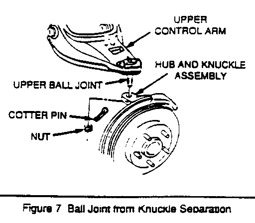
14. Disconnect the cotter pin.
15. Remove the stud nut from the upper ball joint.
16. Loosen the stud using J 34026 and move away from the knuckle (Figure 7).
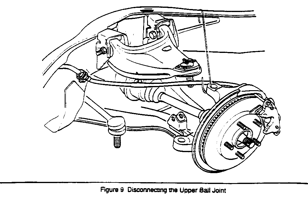
17. Tip the knuckle out and toward the rear of the vehicle. Suspend the knuckle to prevent straining the brake line (Figure 9).
Important: Cover the shock mounting bracket and the ball stud on the lower control arm with a shop towel to prevent possible halfshaft seal damage during removal and installation.
18. Install J28733 on brake rotor and separate outer C/V joint splined shank from knuckle hub (Figure 8).
19. Remove six bolts (loosened earlier) from inboard joint flange (Figure 3).
20. Support inboard end of halfshaft. Free splined shank from hub and remove halfshaft from vehicle.
Important: Wipe the wheel bearing seal area on the knuckle clean. Check the seal for cuts or tears.
21. Lubricate the seal lip.
- If seal is cut or torn, inspect the wheel bearing for damage and replace the seal.
22. If necessary, replace the seal as follows:
- Pry old seal from knuckle and discard. - Lubricate the new seal lip. - Use a flat plate to press the seal down flush with the knuckle.
Tripot Housing/Tripot Seal Replacement
Required Tools:
J8059 Snap Ring Pliers J3591 0 Seal Clamp Tool
1. Place drive axle in vise (use protective covers over vise jaws).
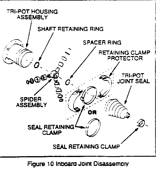
2. Remove seal clamp protectors (Figure 10) if used, from inner C/V joint and cut clamp(s) from seal with a pair of side cutters. For swage ring removal use a hand grinder to cut through the ring (taking care not to damage the housing).
3. Remove tripot housing from halfshaft and wipe grease from tripot assembly roller bearings and housing. Thoroughly degrease the housing and allow to dry prior to assembly.
Important: Handle tripot spider assembly with care. Tripot balls and needle rollers may separate from spider trunnions.
4. Slide seal up on the shaft and inspect rollers, needle bearings, and trunnions. Check housing for unusual wear, cracks, and other damage. Replace housing and/or tripot assembly as needed.
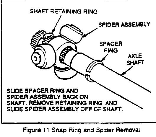
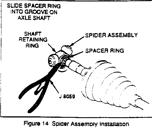
5. To remove the spider assembly (also required for seal replacement), spread the spacer ring with tool J8059 or equivalent and slide the ring and spider assembly up on the shaft (Figure 11). This will provide access to the shaft retaining ring in the groove at the end of the shaft. Remove the retaining ring, spider assembly, spacer ring, and seal.
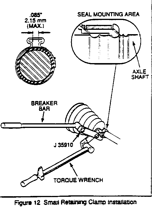
6. Clean the shaft. If rust is present in the seal mounting area (grooves), wire brush this area (Figure 12).
7. Slide the new small seal clamp and seal onto the shaft to the proper position.
8. Secure the clamp with tool J35910, breaker bar and torque wrench. Torque small clamp to 136 N.m (1 00 lbs. ft.). Check clamp ear gap dimension (Figure 12).
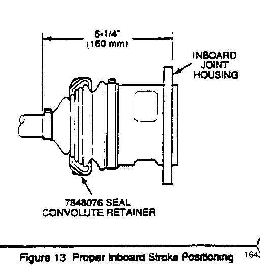
9. Install convolute retainer over seal capturing four convolutes (Figure 13).
Important: Joint must be assembled with convolute retainer in position as shown in Figure 13. Seal damage will result if joint is not assembled to dimension shown.
10. Install spacer ring and spider assembly (with counterbore toward end of shaft) on the shaft far enough to allow installation of the retaining ring at the end of the halfshaft (Figure 14).
11. Install the retaining ring and push the spider assembly toward the end of the shaft until retaining ring is covered by the spider assembly counterbore. Install the spacer ring and make sure it is seated in its groove.
12. Pack the seal and housing with grease supplied in the kit, (the amount of grease supplied in this kit has been premeasured for this application), place the large metal clamp on the seal, then place the housing over the spider assembly and snap the seal onto the housing.
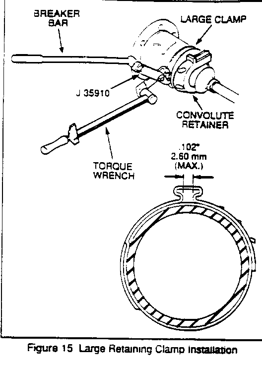
13. Secure the large metal clamp and seal to the housing with tool J3591 0, breaker bar and torque wrench. Torque the large clamp to 176 N.m (130 lbs. ft.). Check clamp ear gap dimension (Figure 15).
Driver Axle Installation:
1. Prior to halfshaft installation, cover shock mounting bracket, lower control arm ball stud, and all other sharp edges with shop towels so that the seal is not damaged during assembly.
2. Remove convolute retainer.
3. Insert and draw up outer C/V joint splined shank into knuckle hub; then secure inboard CN joint flange to companion flange with bolts (do not tighten). Install hub nut washer and nut. Seat shank splines in hub.
4. Connect the upper ball joint to the steering knuckle.
5. Attach the stud nut and torque 83 N.m (61 lbs. ft.).
6. Install new cotter pin.
7. Lubricate the upper ball joint until grease appears at the seal.
8. Remove floor jack or stand from beneath lower control arm, if used.
9. Connect the shock absorber to the lower shock mounting bracket.
10. Attach the shock mounting bolt and nut. Torque the nut and bolt to 73 N.m (54 lbs. ft.).
11. Attach outer tie rod to steering knuckle.
12. Install tie rod nut and torque to 47 N.m (35 lbs. ft.).
Important: Advance the nut to align the nut slot with the cotter pin hole. Never back the nut off to align the cotter pin hole.
13. Install new cotter pin and spread the ends to secure.
14. Attach the brake line support bracket to the upper control arm. Torque to 17 N.m (13 lbs. ft.).
Important: Make sure that the brake hose is not twisted or kinked or damage to the hose could result.
15. Insert a drift-through brake caliper to prevent drive axle from turning and torque inboard flange bolts to 80 N.m (60 lbs. ft.).
16. Torque hub nut to 220-270 N.m (162-199 lbs. ft.).
17. Attach retainer.
18. Align cotter pin hole with retainer slot by rotating retainer.
Important: DO NOT back off or tighten hub nut more than specified to install cotter pin.
19. Install new cotter pin. Cotter pin must be bent so retainer is held snugly to prevent rattling.
20. Remove drift, install wheels, and lower vehicle.
SERVICE PARTS INFORMATION:
Part Number Description Quantity Required ------------ ---------------- ------------------ 26027964 Seal Kit, Tripot 1 per side
Parts are expected to be available on June 17, 1991. Until then normal part orders will not be accepted. by GMSPO. Only verifiable emergency VIP orders will be accepted. GMSPO will make every effort to obtain parts. All parts will be placed on 400 control to waive VIP surcharges. However, the parts will be shipped premium transportation at dealer's expense. All other order types will be canceled as incorrectly ordered while 400 control is in place.
WARRANTY INFORMATION:
Labor Trouble Labor Operation Number Time Code ---------------------- ------ ---- F1500 (Right side) 1.6 92 F1501 (Left side) 1.6 92 F1507 (Both sides) 3.2 92
General Motors bulletins are intended for use by professional technicians, not a "do-it-yourselfer". They are written to inform those technicians of conditions that may occur on some vehicles, or to provide information that could assist in the proper service of a vehicle. Properly trained technicians have the equipment, tools, safety instructions and know-how to do a job properly and safely. If a condition is described, do not assume that the bulletin applies to your vehicle, or that your vehicle will have that condition. See a General Motors dealer servicing your brand of General Motors vehicle for information on whether your vehicle may benefit from the information.
