GM Service Manual Online
For 1990-2009 cars only
Makes
🢒
Isuzu
🢒
2000
🢒
S/T Isuzu - 4WD
🢒
Body and Accessories
🢒
Wiring Systems
🢒 Instrument Cluster: Analog Schematics
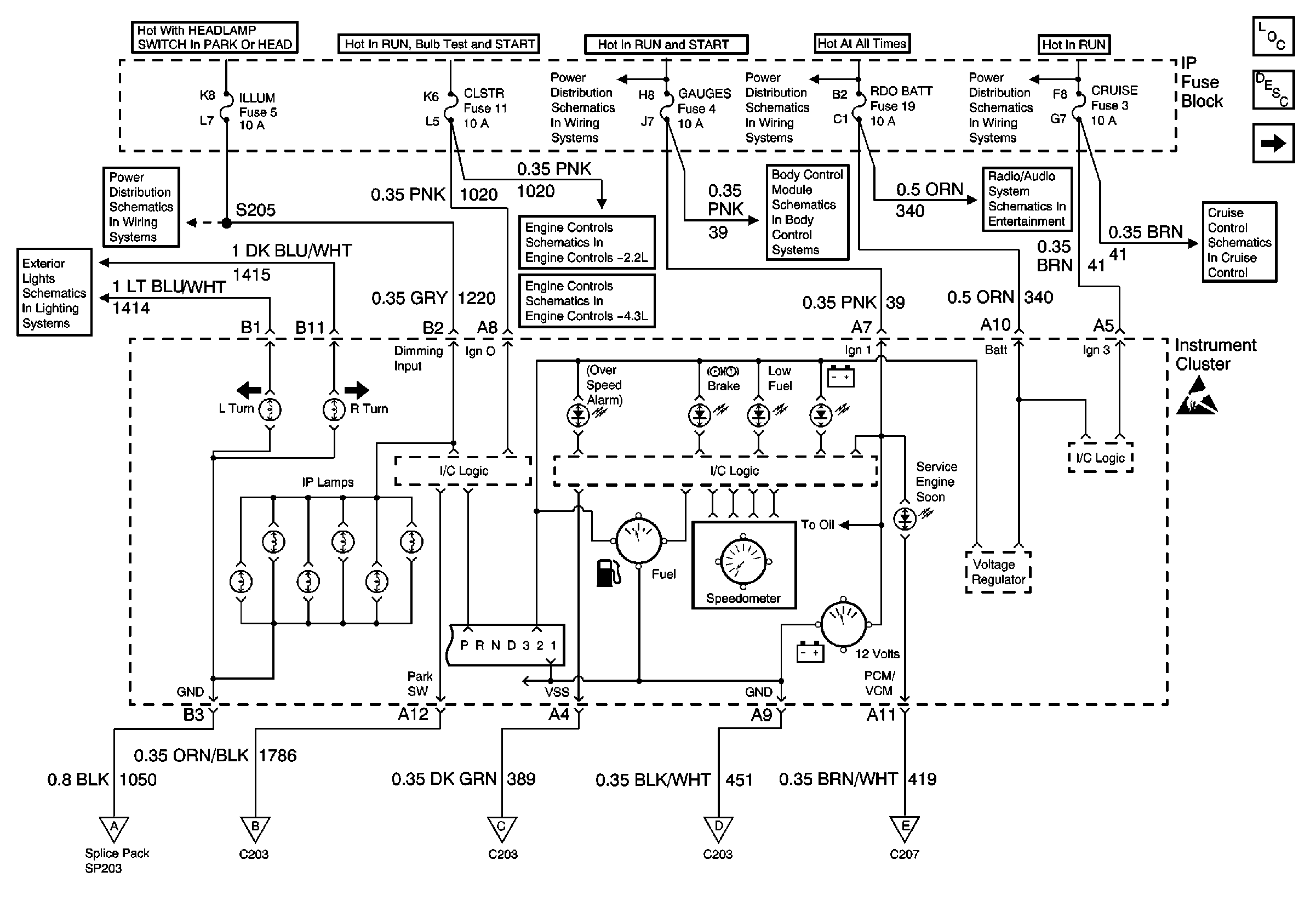
Figure
1:
Power
Instrument Cluster Components
Instrument Cluster Description
Data Link Connector (DLC), PCM/VCM, Engine Oil Pressure Gauge Sensor
Instrument Cluster Turn Signal Indicators
ILLUM Fuse Power
Power, Grounding, Generator and MIL
VCM, CLSTR and 4WD Fuses
IGN C, IGN A Fuses and Ignition and Start Switch
AUX PWR, RDO BATT, HDLP SW Fuses and Inadvertent Power Lamp Relay
Power and Ground
RAP, IGN B Fuses and Ignition Switch
ILLUM, RDO IGN and RDO BATT Fuses and VSS Signal
CRUISE Fuse, Multifunction Switch and Cruise Control Module
Handling ESD Sensitive Parts Notice
Ground
Ground
PCM/VCM
Ground
PCM/VCM
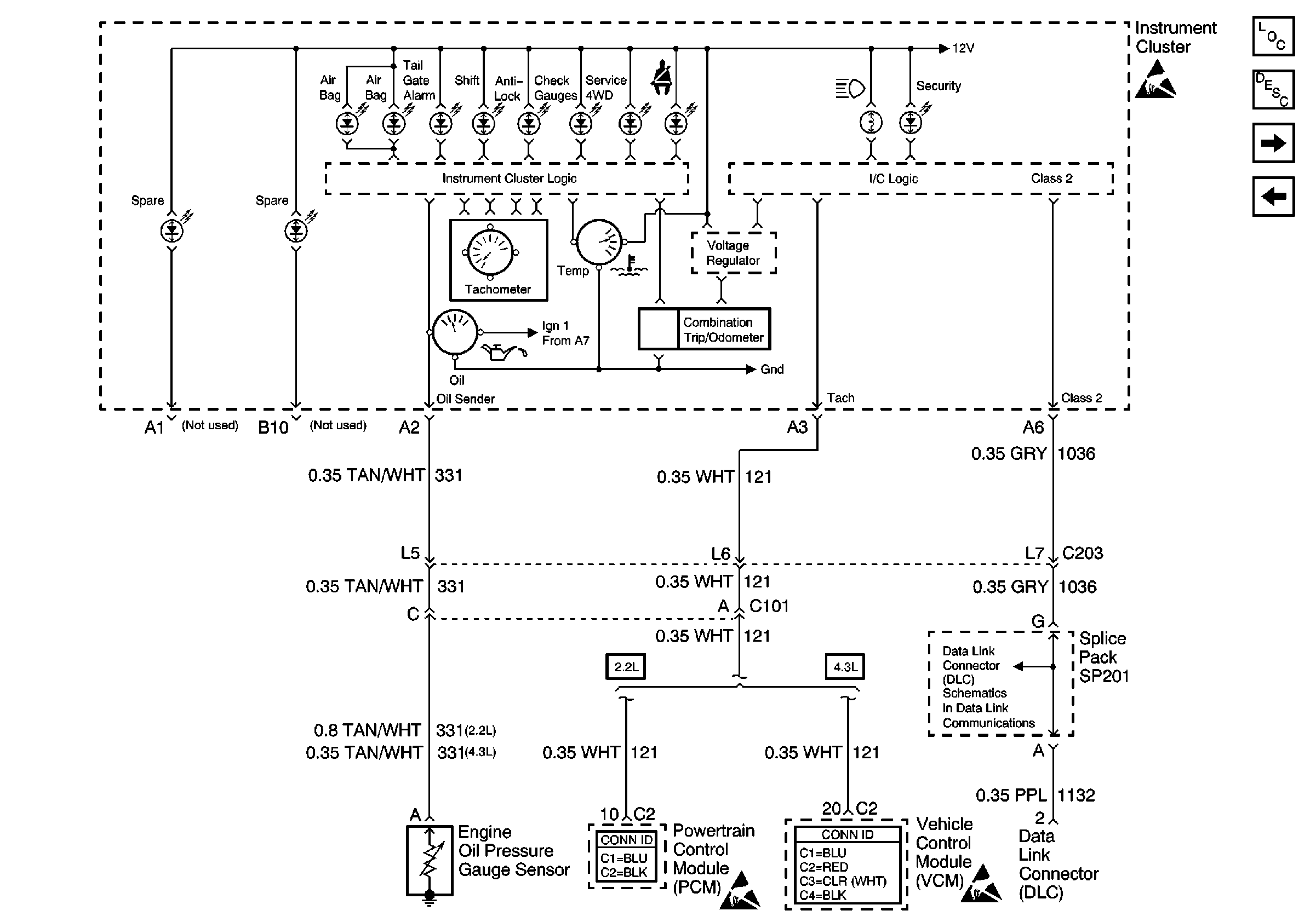
Figure
2:
Data Link Connector (DLC), PCM/VCM, Engine Oil Pressure Gauge Sensor
Instrument Cluster Components
Instrument Cluster Description
Ground
Power
Handling ESD Sensitive Parts Notice
Powertrain Control Module Connector End Views
Handling ESD Sensitive Parts Notice
VCM Connector End Views
Handling ESD Sensitive Parts Notice
SP201 (2.2L)
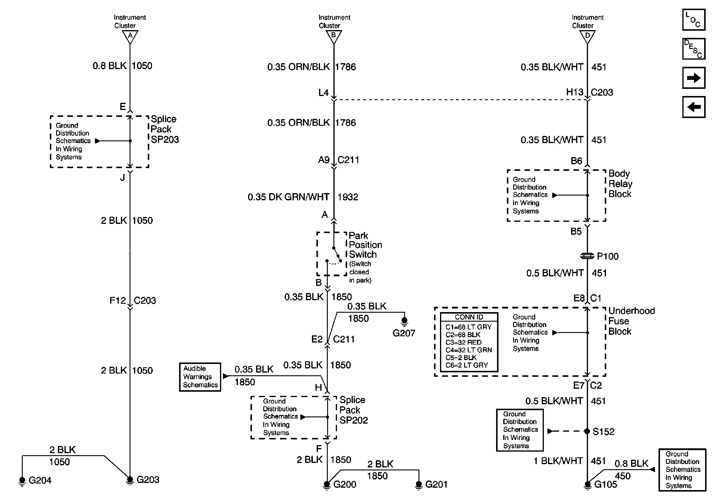
Figure
3:
Ground
Instrument Cluster Components
Instrument Cluster Description
PCM/VCM
Data Link Connector (DLC), PCM/VCM, Engine Oil Pressure Gauge Sensor
Power
Power
Power
G203 and G204
Power and Ground
G200, G201 and G207
G103 and G105 (2.2L)
Power and Grounding Connector End Views
G103 and G105 (2.2L)
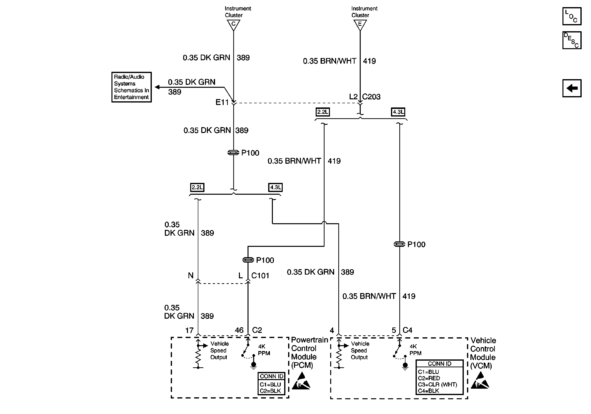
Figure
4:
PCM/VCM
Instrument Cluster Components
Instrument Cluster Description
Ground
Power
Power
ILLUM, RDO IGN and RDO BATT Fuses and VSS Signal
Powertrain Control Module Connector End Views
Handling ESD Sensitive Parts Notice
VCM Connector End Views
Handling ESD Sensitive Parts Notice