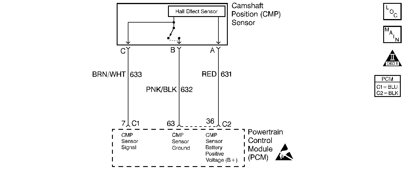
Circuit Description
The camshaft position (CMP) sensor indicates the camshaft position so the powertrain control module (PCM) can determine which cylinder is misfiring when a misfire is present. With the engine running, the CMP activity counter will increment. Whenever the PCM receives an intermittent signal from the CMP, then the CMP resync counter will increment.
Conditions for Running the DTC
Engine is running.
Conditions for Setting the DTC
No change in cam activity for 30 crankshaft revolutions.
Action Taken When the DTC Sets
| • | The malfunction indicator lamp (MIL) will illuminate after two consecutive ignition cycles in which the diagnostic runs with the malfunction present. |
| • | The PCM records the operating conditions at the time when the diagnostic fails. This information stores in the Freeze Frame and Failure Records buffers. |
| • | A history DTC stores. |
Conditions for Clearing the MIL/DTC
| • | The MIL will turn OFF after 3 consecutive ignition cycles in which the diagnostic runs without a fault. |
| • | A history DTC will clear after 40 consecutive warm up cycles without a fault. |
| • | The DTC can be cleared by using the scan tool. |
Diagnostic Aids
| • | Thoroughly check all circuitry for proper mating, broken locks, improperly formed or damaged terminals, or physical damage to the wiring harness. |
| • | Whenever the PCM sees less than 15 resyncs in 256 seconds, the counter resets to 0. Anytime a poor connection is present, the cam sensor activity counter stops incrementing and the cam sensor resync counter starts to increment. |
| • | Inspect the wiring harness for damage. If the harness appears to be OK, observe the CMP resync counter on the scan tool while moving connectors and wiring harnesses related to the CMP sensor. If the CMP resync counter still does not count, then while still observing the scan tool, operate any non-engine related electrical components on the vehicle. A change in display will indicate the location of the malfunction. |
| • | A defective reluctor wheel or a cracked or damaged CMP sensor can result in an intermittent. Remove the camshaft sensor and inspect for any damage. With the CMP sensor removed you can also inspect the reluctor wheel through the hole. Check the porosity and condition of the wheel. The edges must be square, look for a nicked or damaged wheel. |
An intermittent may be caused by any of the following conditions:
| • | A poor connection |
| • | Rubbed through wire insulation |
| • | A broken wire inside the insulation |
Thoroughly check any circuitry that is suspected of causing the intermittent complaint. Refer to Testing for Electrical Intermittents in Wiring Systems.
If a repair is necessary, refer to Wiring Repairs or Connector Repairs in Wiring Systems.
Test Description
The numbers below refer to the step numbers on the diagnostic table.
-
The jumpers let the CMP sensor operate and the technician take readings with the DMM without damaging connector terminals. With a steady idle the DC Hz reading will be from 6.5 to 10.5 Hz.
-
If by disconnecting the jumper for the signal circuit and reading the sensor only gives a good reading, the signal circuit may be shorted to ground.
Step | Action | Values | Yes | No |
|---|---|---|---|---|
1 | Did you perform the Powertrain On-Board Diagnostic (OBD) System Check? | -- | Go to Step 2 | |
2 |
Is the CMP activity counter incrementing at a steady rate? | -- | Go to Step 3 | Go to Step 4 |
3 |
Does the scan tool indicate DTC P0340 failed this ignition? | -- | Go to Step 4 | Go to Diagnostic Aids |
4 |
Is the test lamp illuminated? | -- | Go to Step 5 | Go to Step 10 |
5 | With the CMP sensor connector still disconnected, connect a test lamp from the CMP sensor 12 volt circuit to the CMP sensor return. Is the test lamp illuminated? | -- | Go to Step 6 | Go to Step 11 |
Is the Hz reading at idle within the specified value? | 6.5-10.5 Hz | Go to Step 7 | Go to Step 8 | |
7 |
Was a repair necessary? | -- | Go to Step 14 | Go to Step 13 |
Is the Hz reading at idle within the specified value? | 6.5-10.5 Hz | Go to Step 9 | Go to Step 12 | |
9 |
Was a repair necessary? | -- | Go to Step 14 | Go to Step 13 |
10 | Inspect the CMP 12 volt circuit for an open, short to ground or high resistance. Refer to Wiring Repairs or Connector Repairs in Wiring Systems. Is the action complete? | -- | Go to Step 14 | -- |
11 | Inspect the CMP sensor return for an open or high resistance. Refer to Wiring Repairs in Wiring Systems. Is the action complete? | -- | Go to Step 14 | -- |
12 | Replace the CMP sensor. Refer to Camshaft Position Sensor Replacement . Is the action complete? | -- | Go to Step 14 | -- |
13 |
Important: The replacement PCM must be programmed. Replace the PCM. Refer to Powertrain Control Module Replacement/Programming . Is the action complete? | -- | Go to Step 14 | -- |
14 |
Does the scan tool indicate the diagnostic Passed? | -- | Go to Step 15 | Go to Step 2 |
15 | Does the scan tool display any additional undiagnosed DTCs? | -- | Go to applicable DTC table | System OK |
