Removal Procedure
Tools Required
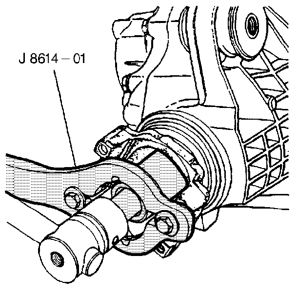
J 8614-01 Flange/Pulley Holder Tool
- In order to free the steering linkage for movement, unlock the steering column.
- Raise the vehicle. Support the vehicle with safety stands. Refer to Lifting and Jacking the Vehicle in General Information.
- Remove the front differential shield. Refer to Shield Replacement .
- Remove the left front differential shield bracket.
- Accurately mark the propeller shaft and pinion flange.
- Remove the bolts from the propeller shaft flange to the front axle. Refer to Double Cardan Universal Joints Replacement in Propeller Shaft.
- Remove the front propeller shaft. Refer to the appropriate procedure in Propeller Shaft:
- Inspect the differential drive pinion bearing preload.
- Inspect the pinion assembly for looseness by moving the pinion back and forth. Looseness indicates excessive bearing wear.
- Remove the pinion flange nut and washer, using the J 8614-01 in order to secure the flange.
- Remove the pinion flange using the J 8614-01 . Provide a suitable container in order to catch the lubricant.
Important: Observe the positions and accurately reference mark all driveline components
relative to the disassembly of the propeller shaft and axles, including the
following components:
• The propeller shafts • The drive axles • The pinion yokes • The output shafts
Important: Note the pinion preload torque for reassembly.
| • | If there is no reading, inspect the drive pinion gear for looseness by shaking the gear. |
| • | When operating the rear axle for an extended period of time with loose bearings or a worn yoke, you will need to replace the ring and pinion gear. |

Installation Procedure
Tools Required
J 8614-01 Flange/Pulley Holder Tool
- Apply special seal lubricant to the outside of the pinion flange.
- Install the new pinion flange.
- Install the washer and a new nut using the J 8614-01 .
- Tighten the nut until the pinion end play is just taken up. Rotate the pinion while tightening the nut in order to seat the bearings. When no end play is present in the pinion, inspect the preload torque.
- Remove the J 8614-01 . Inspect the pinion preload torque wrench. Preload should be at or below 2.7-3.6 N·m (24-32 lb in) on new bearings. or within 1.0-1.4 N·m (8-12 lb in) for used bearings.
- If the preload torque is below the specified values, continue torquing the nut in small increments. Inspect the preload after each tightening. Each tighten increases the bearing preload by several hundred pounds. If the bearing preload is exceeded remove the pinion and install a new collapsible spacer.
- Once the specified preload has been obtained, rotate the pinion several times in order to ensure that the bearings have seated. Recheck the preload, and adjust if necessary.
- Install the propeller shaft. Refer to the appropriate procedure in Propeller Shaft:
- Install the bolts to the flange.
- Inspect the axle lubricant level. Add lubricant as necessary. Refer to Fluid and Lubricant Recommendations in Maintenance and Lubrication.
- Install the left front differential shield bracket.
- Install the differential shield. Refer to Shield Replacement .

Notice: Use the correct fastener in the correct location. Replacement fasteners must be the correct part number for that application. Fasteners requiring replacement or fasteners requiring the use of thread locking compound or sealant are identified in the service procedure. Do not use paints, lubricants, or corrosion inhibitors on fasteners or fastener joint surfaces unless specified. These coatings affect fastener torque and joint clamping force and may damage the fastener. Use the correct tightening sequence and specifications when installing fasteners in order to avoid damage to parts and systems.
Tighten
Tighten the bolts to 75 N·m (55 lb ft).
