Checking with Gauges
The various types of frame misalignment may be divided into the following groups:
| • | Sag |
| • | Buckle |
| • | Diamond |
| • | Side sway |
| • | Twist |
A misaligned frame may have moved forward or rearward from, upward or downward from, or to the side of the frame's original position. Inspect the vehicle when such conditions are present. The most efficient way to check frame alignment is to use gauges. Detailed instructions are normally supplied with the gauges at the time of purchase. You can, however, check the frame alignment without gauges. Refer to Checking without Gauges.
Whether you check alignment with or without gauges, park the vehicle on a level section of the floor.
Certain conditions call for some preliminary checks before actually checking the frame. Suspension or axle problems may be mistaken for frame misalignment. For example, a shifted axle may appear to be frame diamond or side sway. A weak spring may appear to be a twisted frame.
A visual inspection on the top and the bottom of the flanges of each rail may reveal an area on which sag or buckle exist. In the case of sag, wrinkles will appear on the top of the upper flange. Such wrinkles are definite evidence of sag. Wrinkles on the bottom or the lower flange are definite evidence of frame buckle.
Checking without Gauges
- Move the vehicle to a level, well-lit section of the floor.
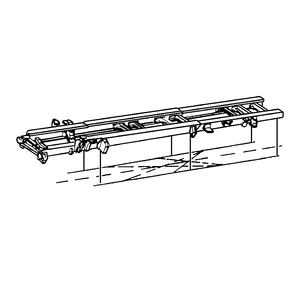
- Make a diagram of the frame on the floor under the vehicle.
- Pick several points on the bottom flange of each of the frame rails. Leave clear access from these points to the floor. Mark one point at the rear end of each of the rails. Ensure that all of the points are the same distance from the vertical part (web) of the rail.
- Use a plumb bob to transfer the points on the rails to the floor directly beneath the rails.
- Move the vehicle away from the points on the floor.
- Mark a chalk line through the points representing each of the rails.
- Measure the distance between each point and the line representing the rail. The distance should be not be more than 3 mm (0.12 in). A distance greater than 3 mm (0.12 in) indicates side sway.
- Measure the distance between the web at the end point of the rear section of the rails. The distance should measure 851 mm (31.5 in).
- Measure the distance between the inside of the frame rails at the front of the frame. This distance should be 851 mm (31.5 in).
- Measure the length of each of the rail lines. Each rail line should be the same length.
- Mark a point on one of the rail lines, a given distance from one end of the vehicle. Mark a point on at the same spot on the other rail line.
- Mark a pair of diagonals from the 2 points on the rail lines to the opposite rail. Make the diagonals the same length.
- Mark a second pair of diagonals from the original 2 points on the rail lines to the opposite rails. The second pair of diagonals should be the same length as each other, but longer than the first pair of diagonals.
- Mark a line between the points of the intersection of the 2 pairs of diagonals. This line should be the same distance from each of the frame rails at any given point along their edges.

The following steps offer an alternative method of checking the vertical alignment of a normally straight rail:
- Measure the distance from the frame rail to the floor at several different points along the rail. The vehicle must be on a level section of the floor.
- Transfer these distances, in order, to a sheet of graph paper.
- Connect the points, representing each distance, on the graph paper.
- If the rail is straight (vertically), the points should all lie on a straight line.
