Removal Procedure
Important: The following transmission replacement procedure serves as a guide.
In order to provide enough clearance for removal of the transmission, removal
of other components may be necessary on some vehicles. Information
on the removal of other components are not included in this transmission
replacement procedure.
- Block the wheels.
Caution: Unless directed otherwise, the ignition and start switch must be in the OFF or LOCK position, and all electrical loads must be OFF before servicing
any electrical component. Disconnect the negative battery cable to prevent an electrical spark should a tool or equipment come in contact with an exposed electrical terminal. Failure to follow these precautions may result in personal injury and/or damage to
the vehicle or its components.
- Disconnect
the negative battery cable.
- Drain the transmission oil. Refer to
Automatic Transmission Fluid and Filter Replacement
.
- Cover the oil pan opening in order to prevent the entry of foreign
material.

- Remove the transmission
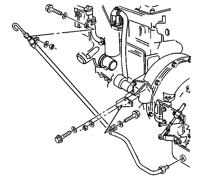
oil level indicator and the oil level indicator tube. Refer to
Transmission Fluid Filler Tube and Seal Replacement
.

- Disconnect the oil cooler lines from the transmission. Refer to
Oil Cooler Hose/Pipe Replacement
.

- Disconnect the shift cable
from the transmission. Refer to
Shift Cable Replacement
.
- Remove the modulator from the transmission.
- Disconnect the wiring harness and the connectors from the transmission.
- Disconnect the speedometer sensor harness from the transmission.
- Remove the propeller shaft. Refer to the necessary procedure:
- Disconnect the parking brake cable, if equipped. Refer to
Park Brake Cable Replacement
.

NOTICE: Carefully inspect the transmission and the surrounding areas to be sure
no lines, hoses or wires will interfere with the transmission removal. In
order to avoid damage to the transmission or the torque converter, support
the transmission with a dolly jack. Do not let the torque converter fall.
- Determine
what type of front engine mount is on the vehicle and take the following steps
when removing the rear engine mounting bolts:
| • | If the mount is a single cushion, center mount, support the engine
with an overhead hoist during the transmission replacement in order to prevent
tipping. |
| • | If the rear engine mounting bolts are not attached to the engine
flywheel housing, support the rear of the engine on a jack stand. |
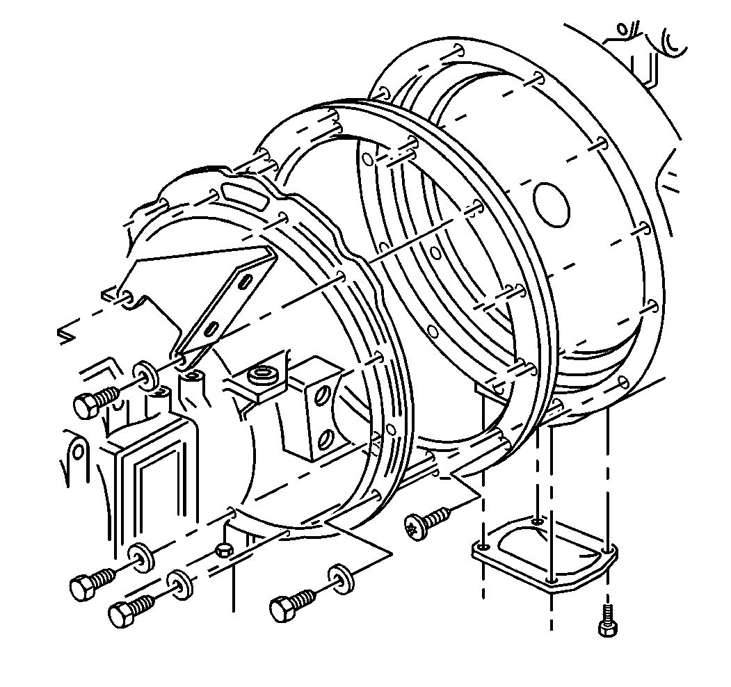
| 13.1. | Remove the flywheel housing access cover. |
| 13.2. | Turn the flex plate using a pry bar in order to align the torque
convertor bolts with the access hole. |
| 13.3. | Remove the torque convertor bolts. |
- Remove the transmission rear support beam, if equipped.
- Remove the rear engine mounting bolts, if the mounts are not attached
to the engine flywheel housing.
- Support the rear of the engine on a jack stand.

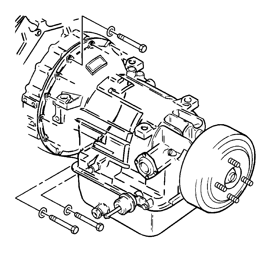
- Remove the bolts securing the transmission to the engine.

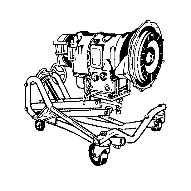
- Support the transmission
with a transmission dolly that can support a load of at least 349 kg
(750 lb).
| 18.1. | Position the dolly in order to ensure the transmission oil pan
does not support the weight of the transmission. |
| 18.2. | Fasten a safety chain over the top of the transmission. Fasten
the chain on both sides of the dolly. |
| 18.3. | Lower the transmission. |
| 18.4. | Remove the transmission from the vehicle. |
Installation Procedure

NOTICE: Carefully inspect the transmission and the surrounding area to be sure
no lines, hoses or wires will interfere with the transmission installation.
When raising and moving the transmission, do not let the torque converter
slip off the shaft. The transmission or torque converter can be damaged.
- Use a transmission dolly that can support a load of at least 349 kg
(750 lb) to lift the transmission into place.
| 1.1. | Move the transmission forward. |
| 1.2. | Align the torque converter with the pilot hole in the engine flex
plate. |
| 1.3. | Secure the transmission to the engine. |

Notice: Use the correct fastener in the correct location. Replacement fasteners
must be the correct part number for that application. Fasteners requiring
replacement or fasteners requiring the use of thread locking compound or sealant
are identified in the service procedure. Do not use paints, lubricants, or
corrosion inhibitors on fasteners or fastener joint surfaces unless specified.
These coatings affect fastener torque and joint clamping force and may damage
the fastener. Use the correct tightening sequence and specifications when
installing fasteners in order to avoid damage to parts and systems.
- Install the transmission
to engine bolts.
Tighten
Tighten the transmission to engine bolts to 55 N·m (41 lb ft).

- Turn the engine flex plate
using a pry bar in order to install the torque converter to flywheel bolts.
- Install the torque converter to flywheel bolts.
Tighten
Tighten the torque converter to flywheel bolts to 67 N·m
(49 lb ft).
- Install the flywheel housing access cover.
- Install the transmission rear support beam, if equipped.
- Install the transmission rear support beam to transmission nuts.
Tighten
Tighten the support beam nuts to 105 N·m (77 lb ft).
- Install the rear engine mount bolts.
- Install the cushion, the bolts, and the washers to the frame bracket,
if equipped.
Tighten
Tighten the cushion to the bracket nuts to 45 N·m (33 lb ft).
- Install the cushion to support nuts and the shims, as needed.
Tighten
Tighten the cushion to support nuts to 31 N·m (23 lb ft).
- Connect the parking brake cable. Refer to
Park Brake Cable Replacement
.

- Connect the oil cooler lines to the transmission. Refer to
Oil Cooler Hose/Pipe Replacement
.

- Install the oil level
indicator tube. Refer to
Transmission Fluid Filler Tube and Seal Replacement
.
- Connect the speedometer sensor harness.
- Install the propeller shaft to the transmission. Refer to the
necessary procedure:
- Install the modulator to the transmission.

- Connect the shift cable
to the transmission. Refer to
Shift Cable Replacement
.
- Connect any additional lines, hose, or wires, as required.
- Fill the transmission with oil. Refer to
Automatic Transmission Fluid and Filter Replacement
.
Caution: Unless directed otherwise, the ignition and start switch must be in the OFF or LOCK position, and all electrical loads must be OFF before servicing
any electrical component. Disconnect the negative battery cable to prevent an electrical spark should a tool or equipment come in contact with an exposed electrical terminal. Failure to follow these precautions may result in personal injury and/or damage to
the vehicle or its components.
- Connect
the negative battery cable.
- Check the transmission oil level. Refer to
Fluid Capacity Specifications
.
- Remove the wheel blocks.


