GM Service Manual Online
For 1990-2009 cars only
Makes
🢒
Isuzu
🢒
2007
🢒
I-290
🢒
Diagnostic Navigation
🢒
Vehicle Diagnostic Information
🢒 Transfer Case Control Schematics
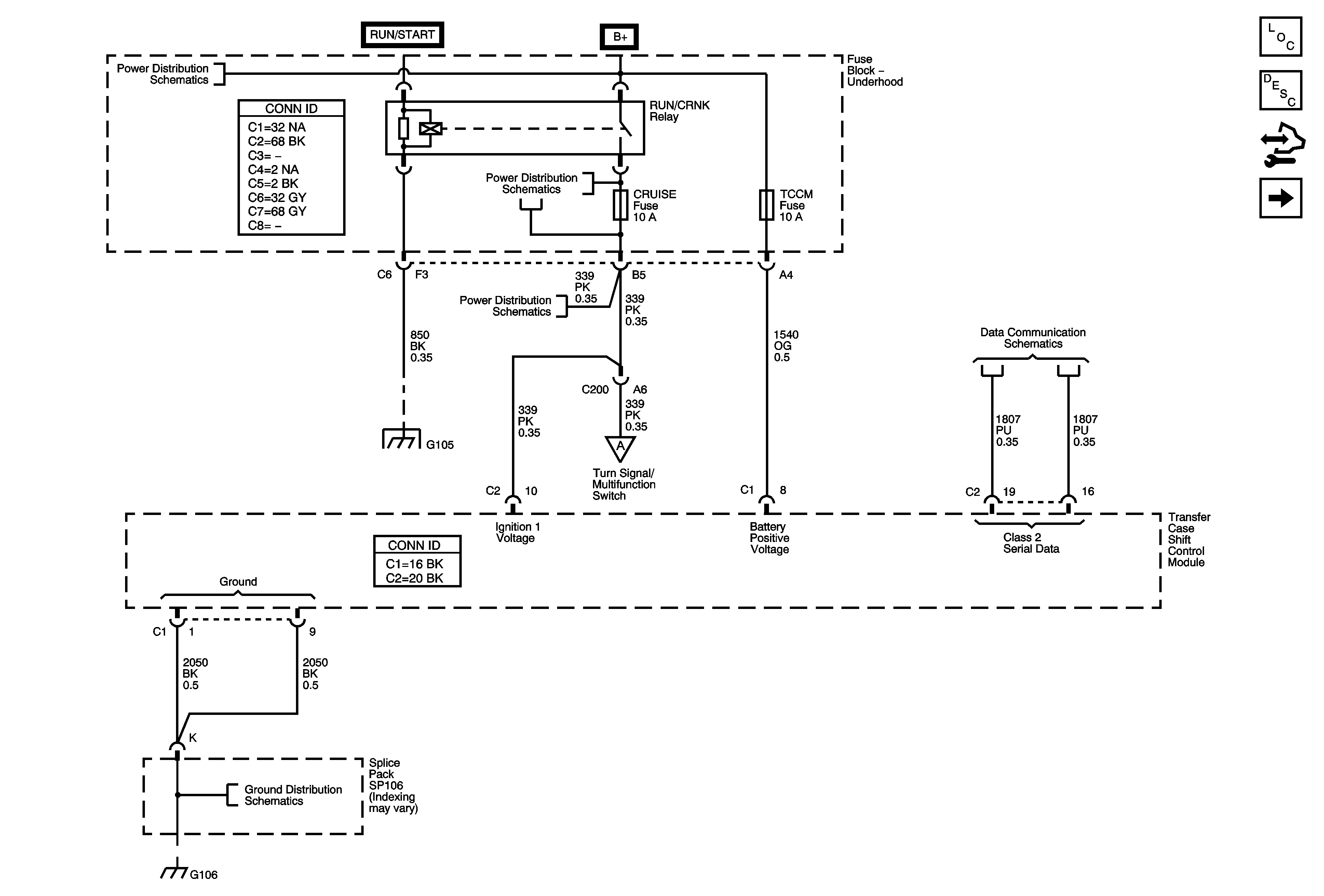
Figure
1:
Power, Ground, and DLC
Master Electrical Component List
Transfer Case Description and Operation
Body Control Module Programming and Setup
Transfer Case Encoder Motor
B+ Bus - Underhood Fuse Block
Splice Pack SP105 and G105 - 1 of 2
RUN/CRANK RELAY BUS - 1 of 3, CRUISE, SIR, and TRANS Fuses
Shift Control Switch Inputs
Data Communication Schematics
Splice Pack SP106 and G106 - 2 of 2
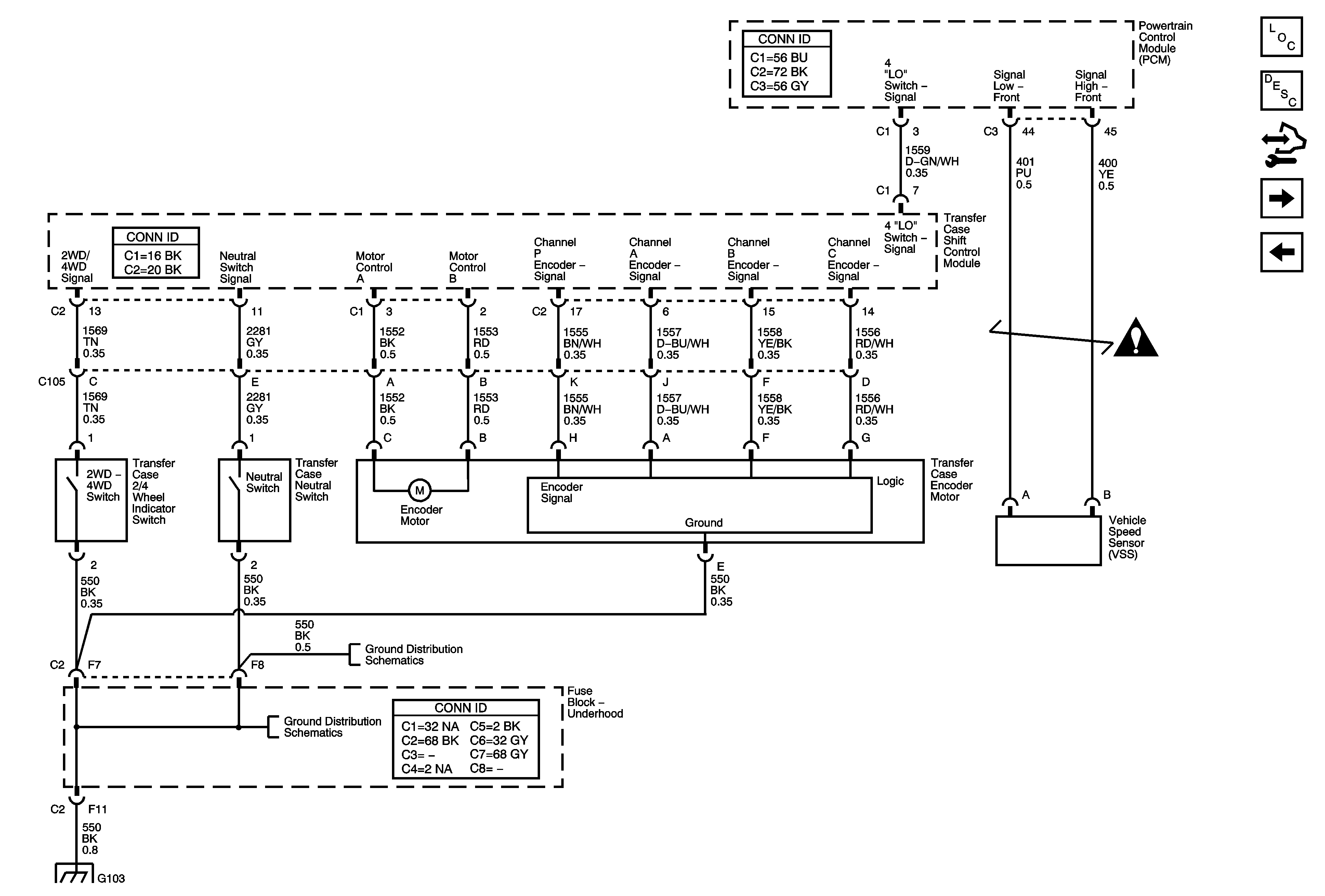
Figure
2:
Transfer Case Encoder Motor
Master Electrical Component List
Transfer Case Description and Operation
Body Control Module Programming and Setup
Front Axle Actuator
Power, Ground, and DLC
Transfer Case Control Schematic Icons
G100, G104, G102, G103
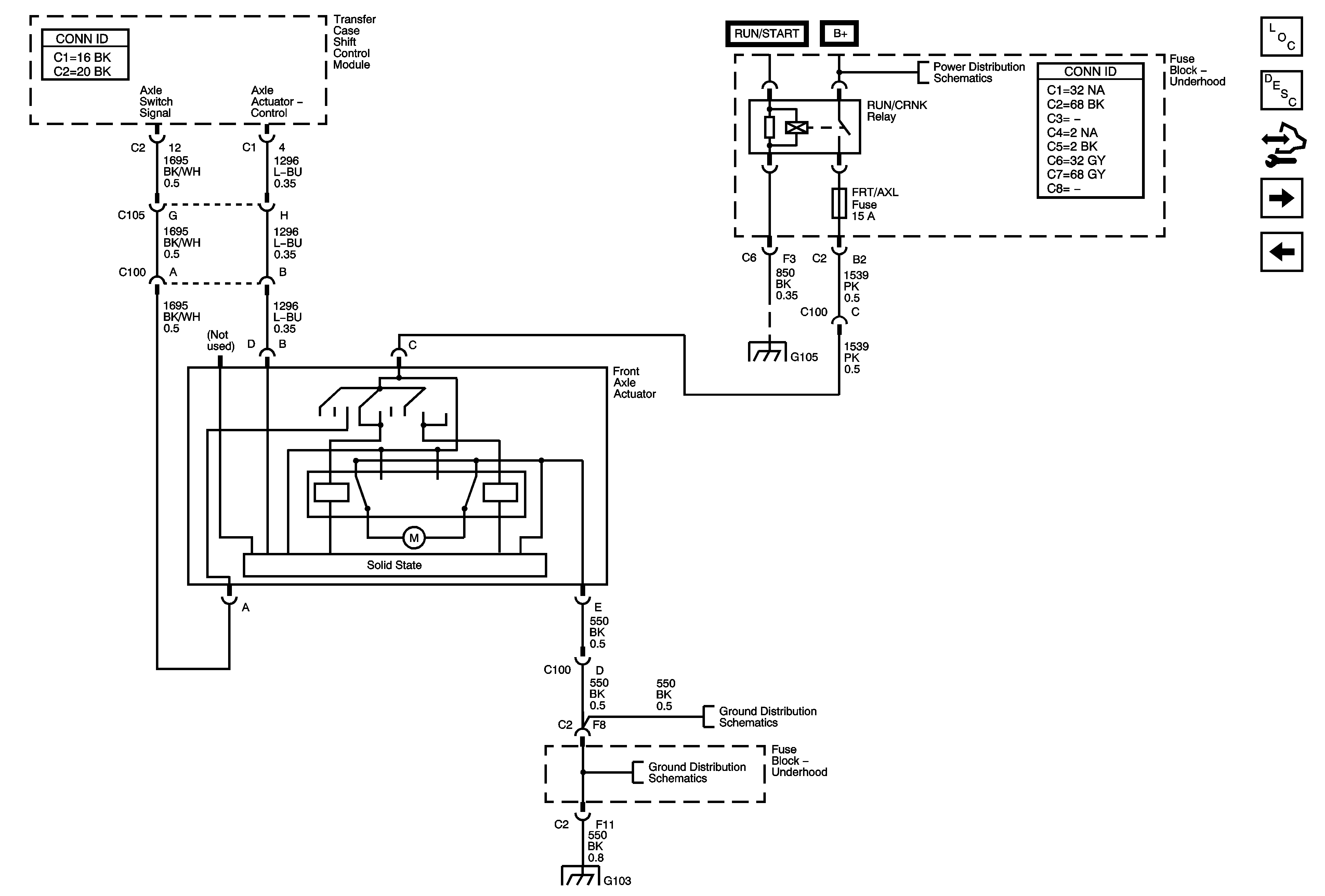
Figure
3:
Front Axle Actuator
Master Electrical Component List
Transfer Case Description and Operation
Body Control Module Programming and Setup
Shift Control Switch Inputs
Transfer Case Encoder Motor
B+ Bus - Underhood Fuse Block
Splice Pack SP105 and G105 - 1 of 2
G100, G104, G102, G103
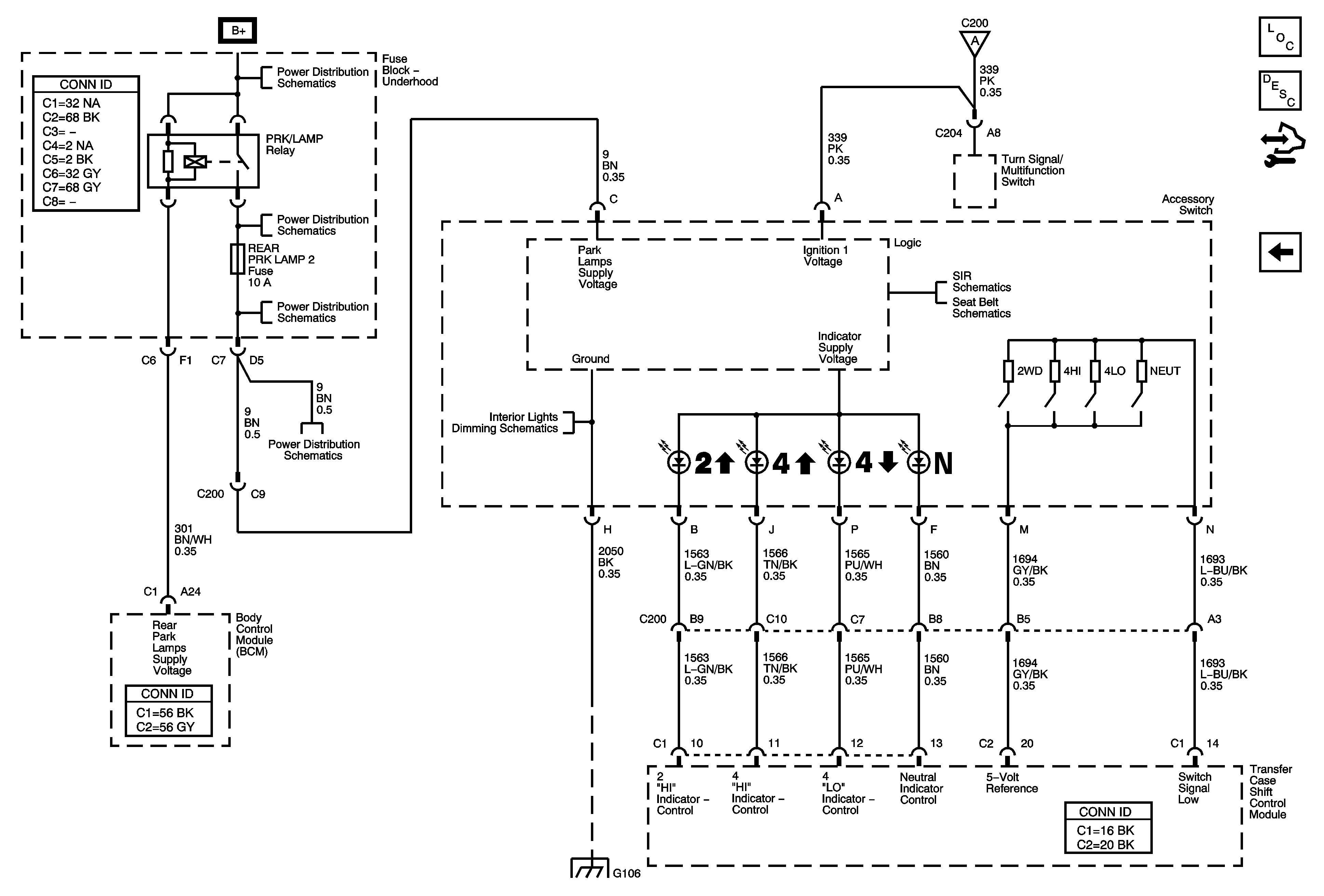
Figure
4:
Shift Control Switch Inputs
Master Electrical Component List
Transfer Case Description and Operation
Body Control Module Programming and Setup
Front Axle Actuator
B+ Bus - Underhood Fuse Block
FR PK LP, RR PK LP, and RR PK LP2 Fuses
Interior Lights Dimming Schematics
Splice Pack SP106 and G106 - 2 of 2
Power, Ground, and DLC
PPS Sensors and Indicators
Seat Belt Schematics