Tools Required
J 8433 Two Jaw Puller
Important: The following steps apply to both the 4WD
and the RWD transmission, except where noted.
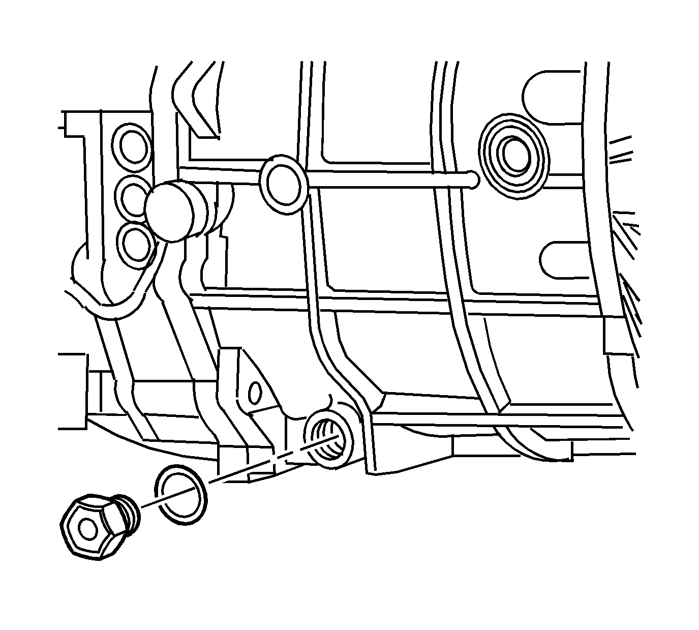
- Remove the drain plug, with aluminum washer, and drain the transmission fluid.
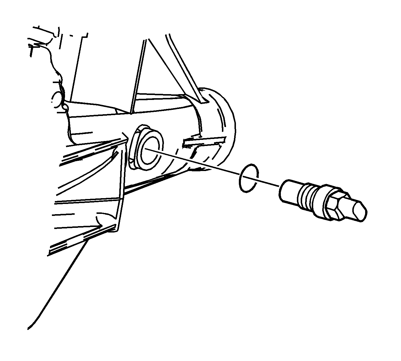
- If RWD, remove the vehicle speed sensor with O-ring
seal.
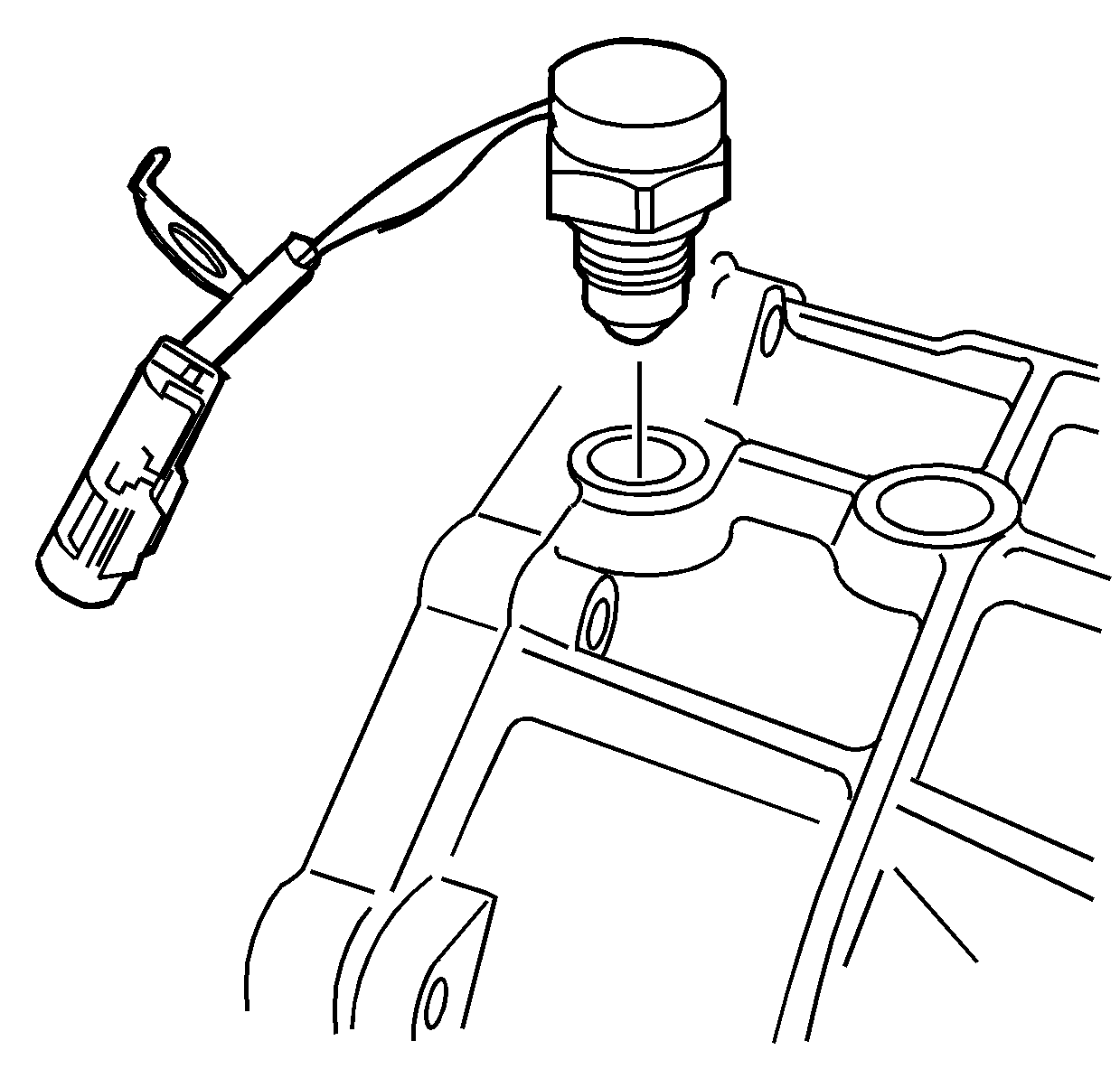
- Remove the backup lamp switch, with the aluminum washer,
from the front case.
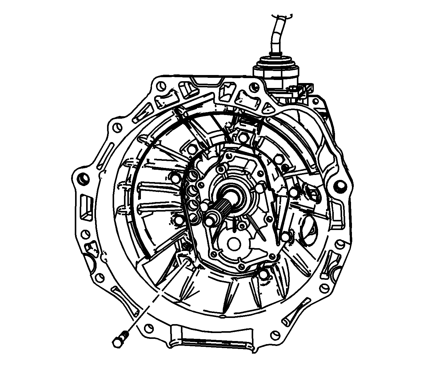
- Remove the 9 bolts retaining the clutch housing.
- Using a soft-face hammer, remove the clutch housing from the transmission
assembly.
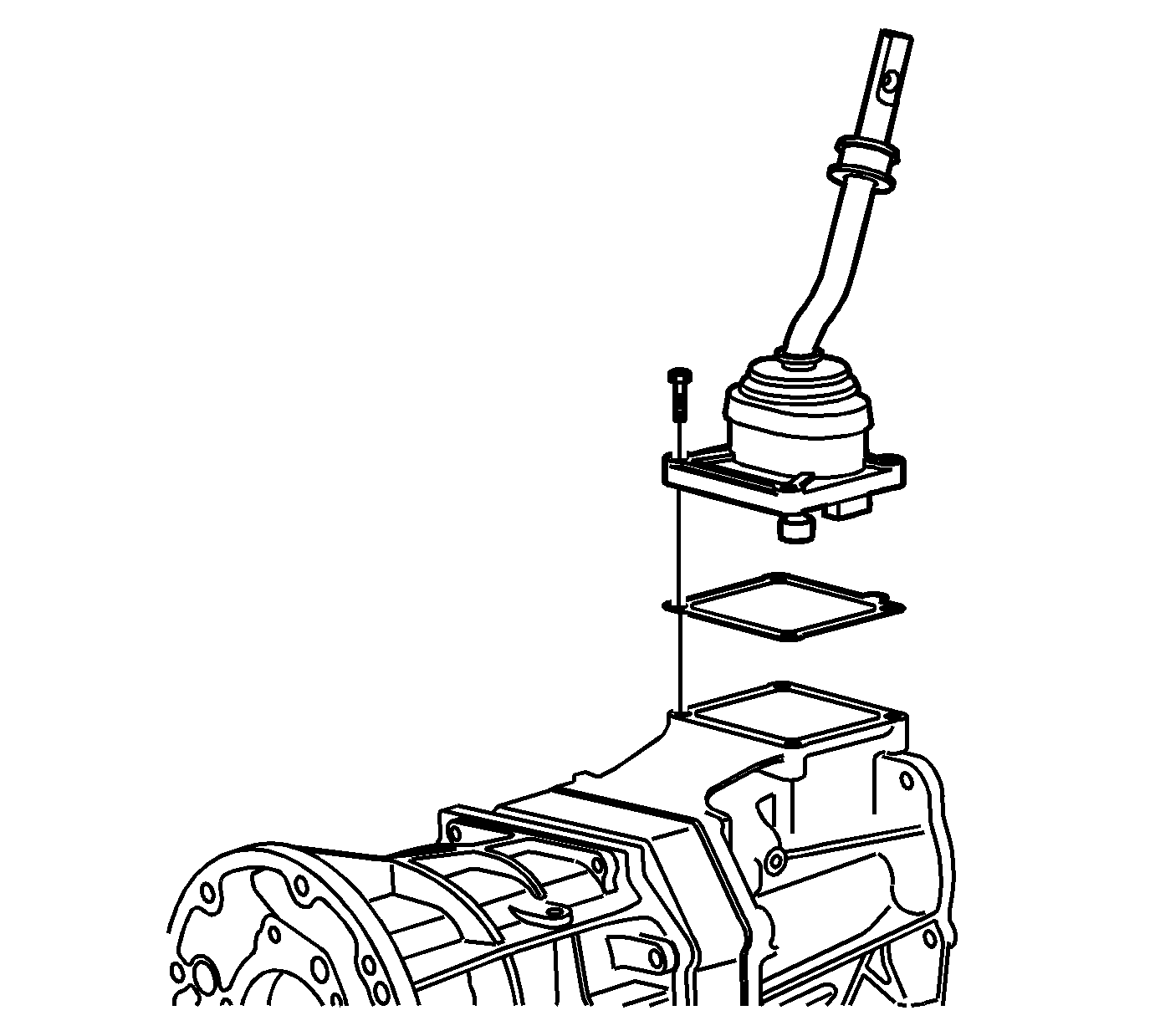
- Shift the transmission into NEUTRAL.
- Remove the shift control housing bolts.
- Remove the shift control housing.
- Remove the shift control housing gasket.
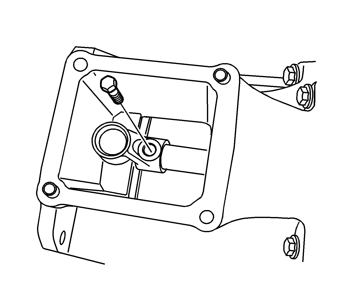
- Remove the shift control lever socket bolt.
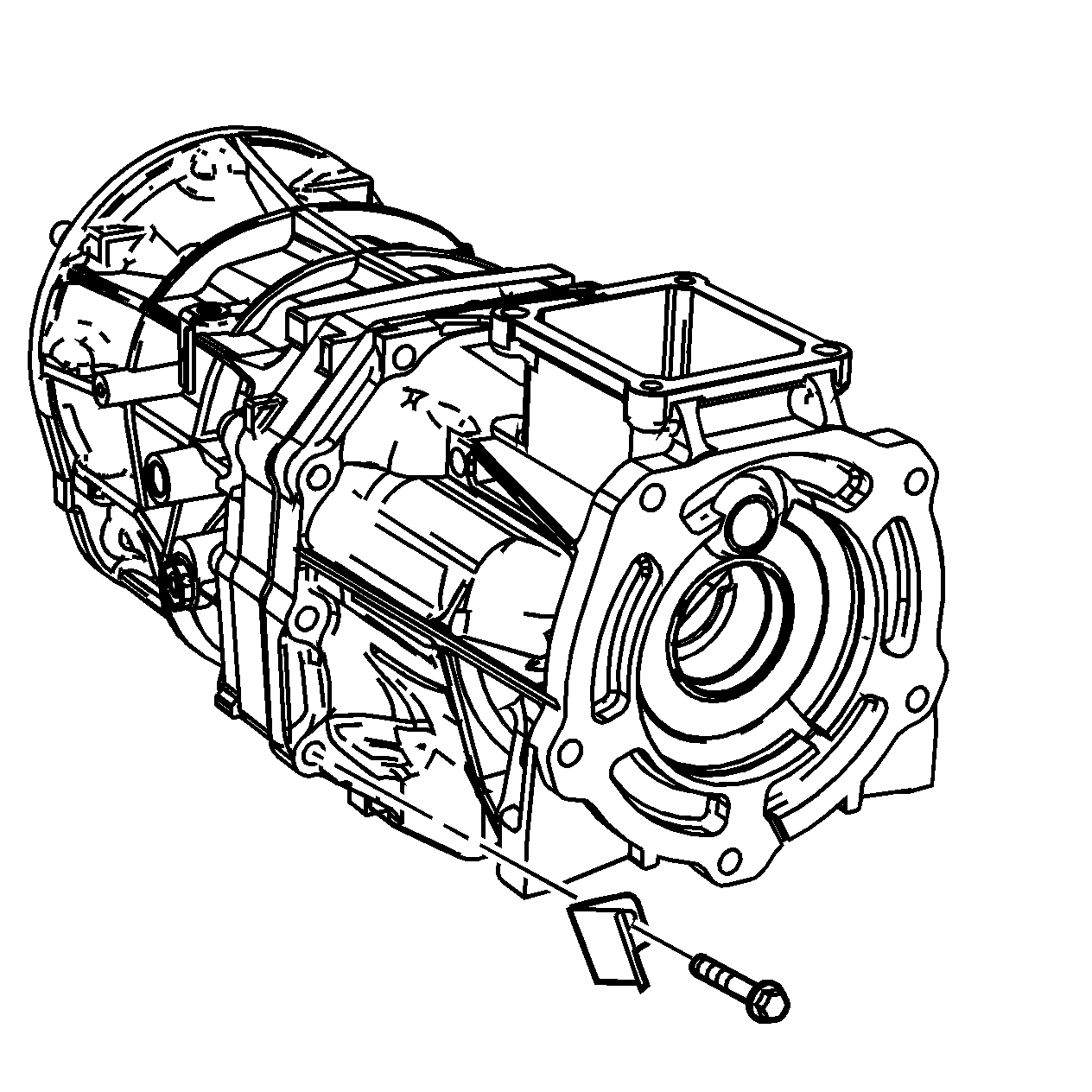
- Mark the location of the brackets and the studs.
- Remove the extension housing retaining bolts, studs, and brackets.
The 4WD does not use a bracket on the left side of the transmission.
Notice: Refer to Machined Surface Damage Notice in the Preface section.
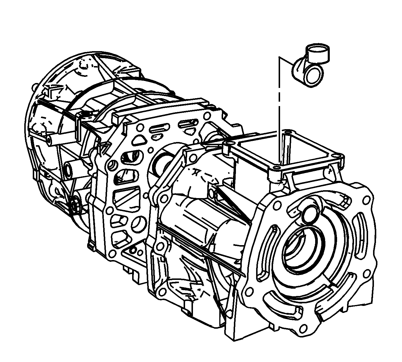
- Using a soft-face hammer, separate the extension housing from the intermediate
case.
- Slide the extension housing off the shift control shaft.
- Remove the shift control socket from the extension housing shift lever
cavity.
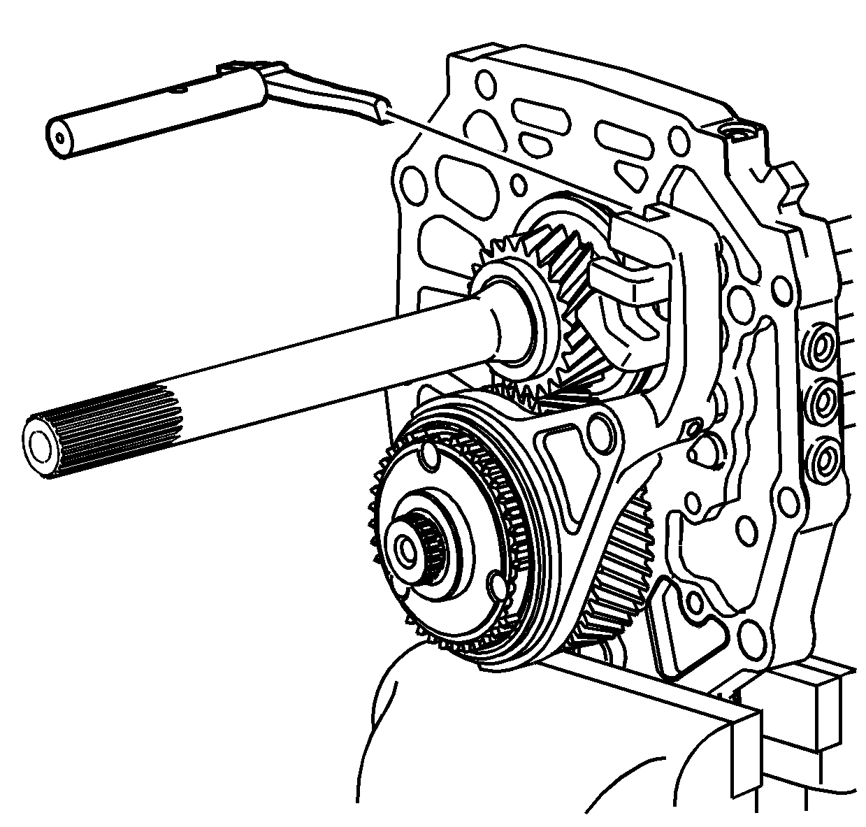
- Remove the shift control shaft from the shift shaft
gates.
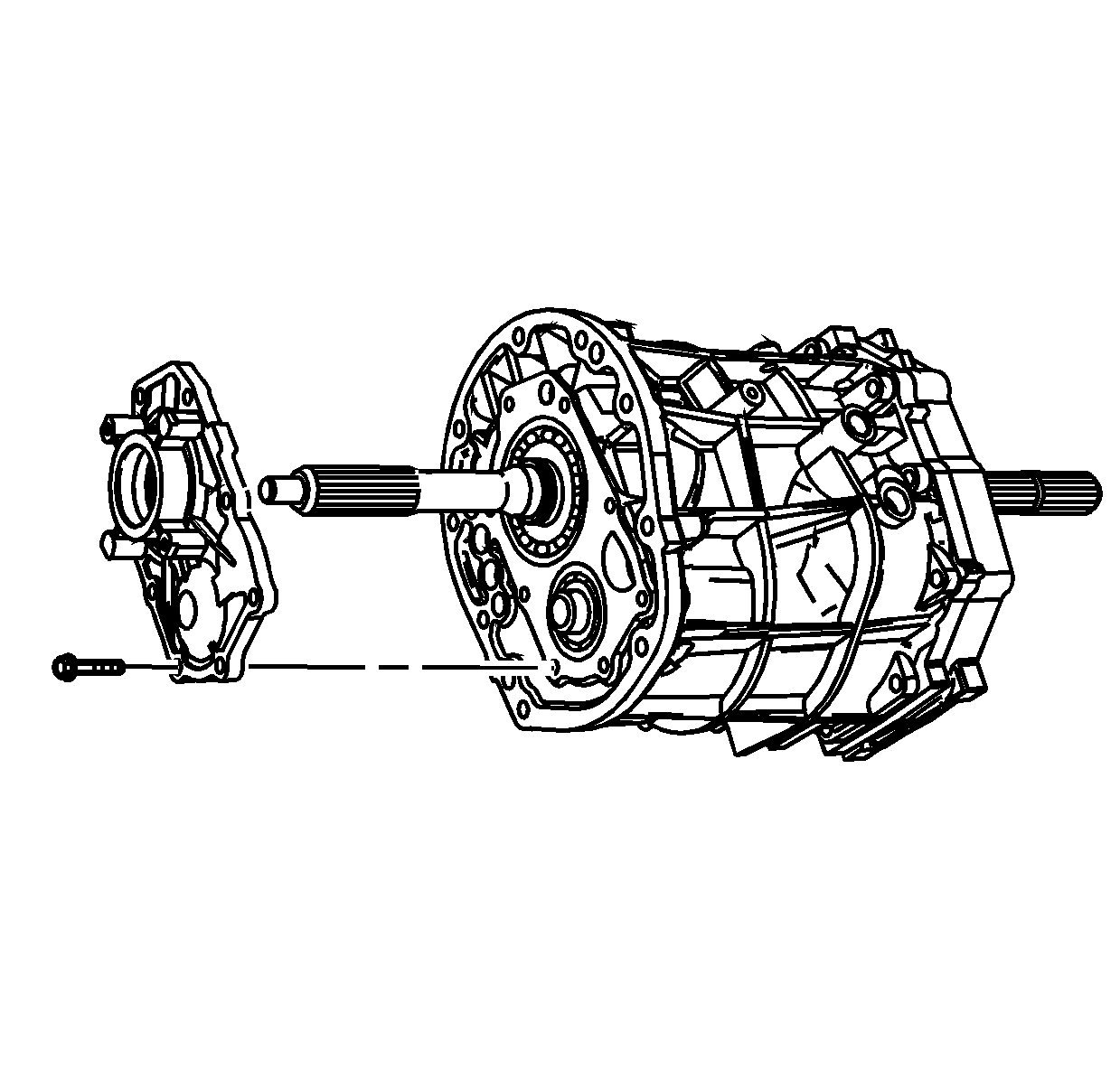
- Remove the front bearing retainer bolts. Discard the
bolts. New bolts are required for assembly.
- Remove the front bearing retainer.
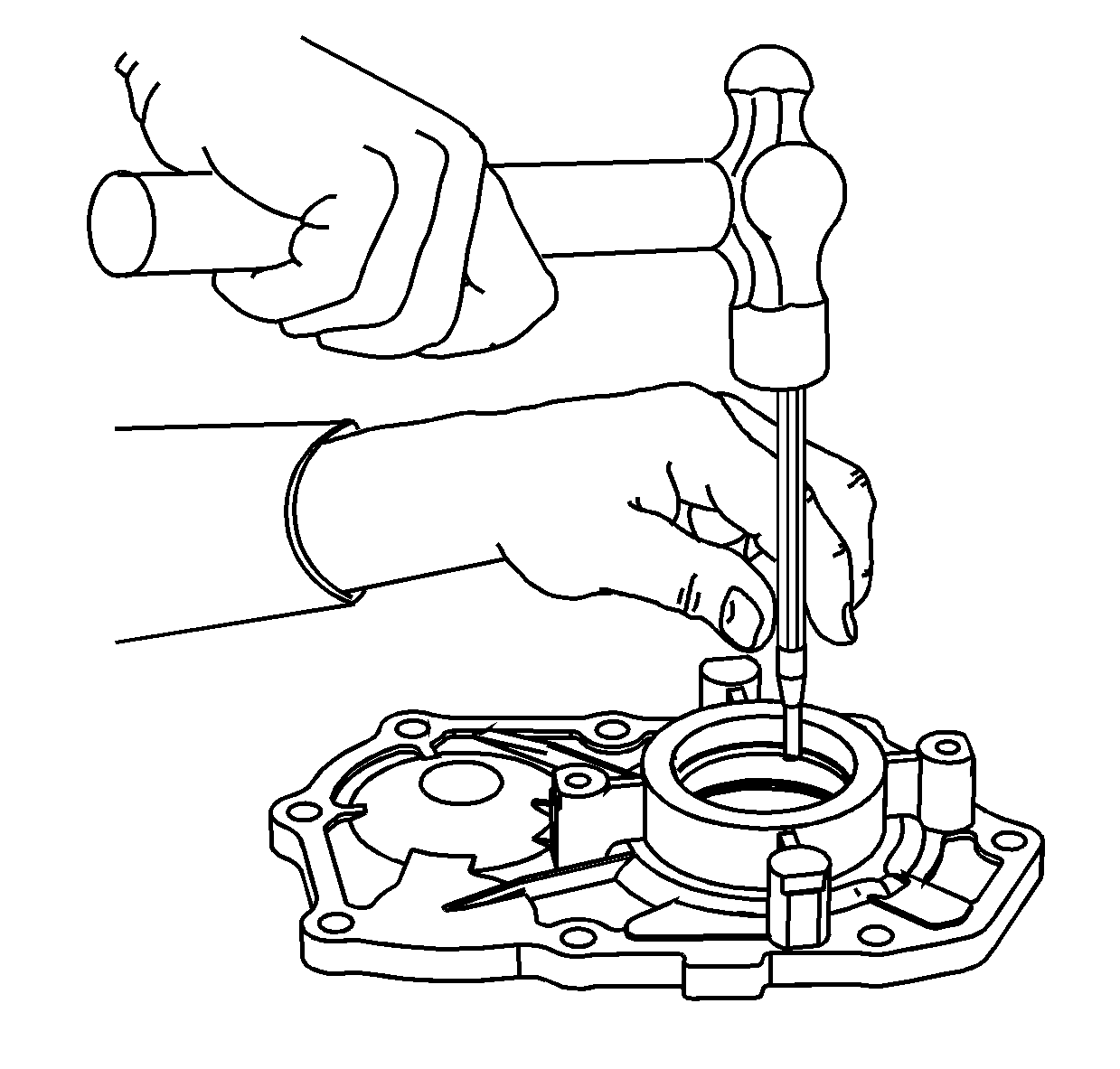
- Using a suitable punch and a hammer, remove the input
shaft seal from the bearing retainer. Do not use the seal again.
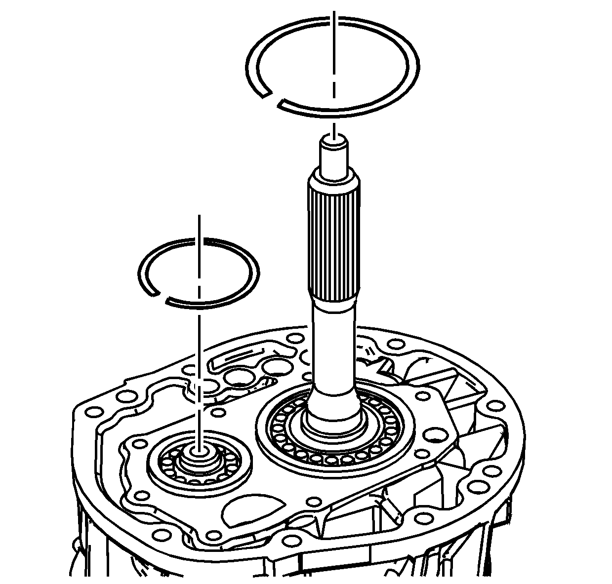
- Remove the outer retaining ring from the input shaft
bearing.
- Remove the outer retaining ring from the countershaft front bearing.
Notice: Refer to Machined Surface Damage Notice in the Preface section.
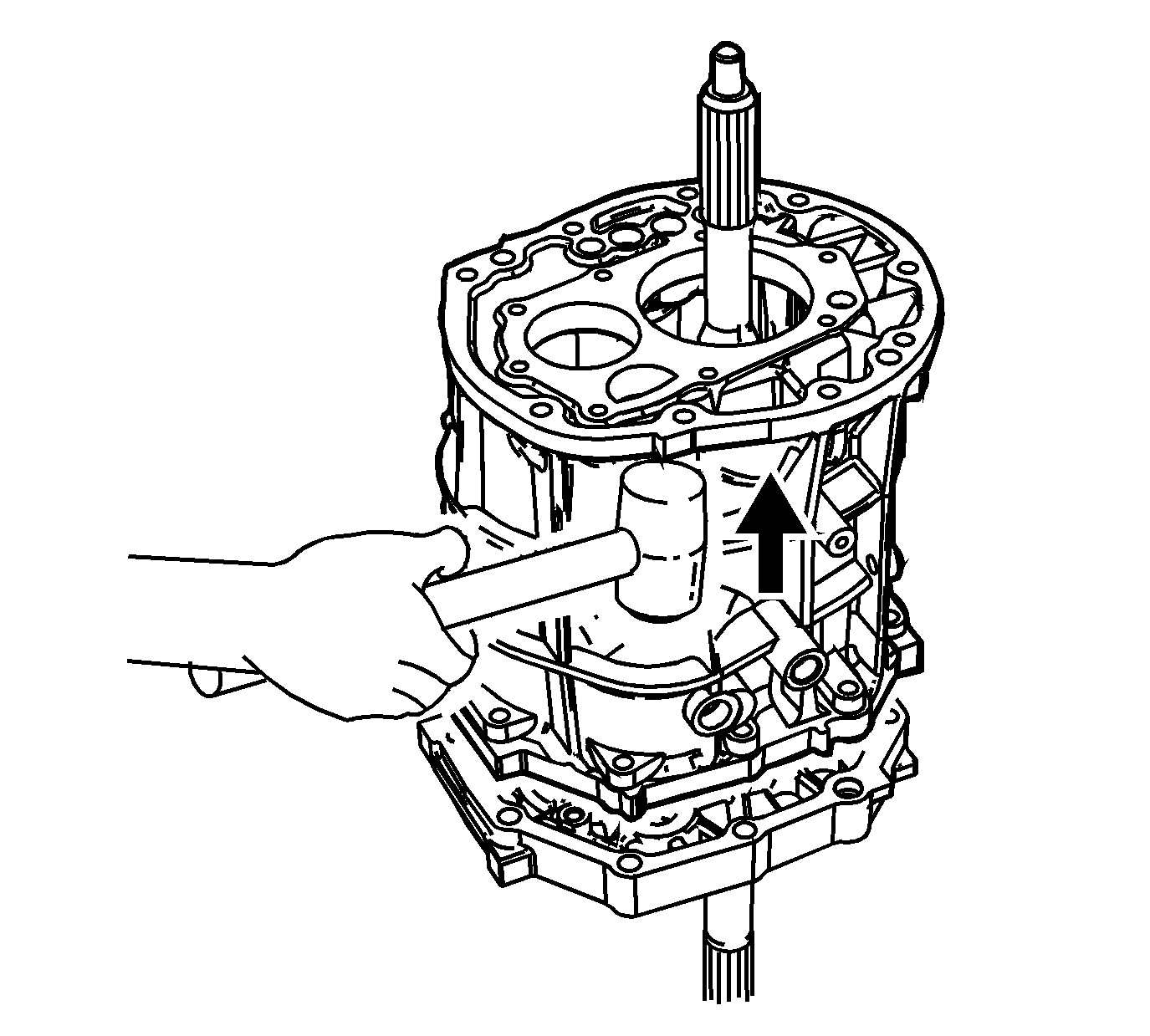
- Using a soft-face hammer on the transmission front case, shear the sealer.
- Remove the transmission front case from the intermediate case.
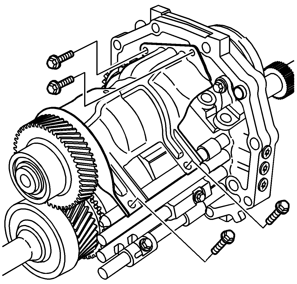
- Remove the oil baffle bolts.
- Remove the oil baffle.
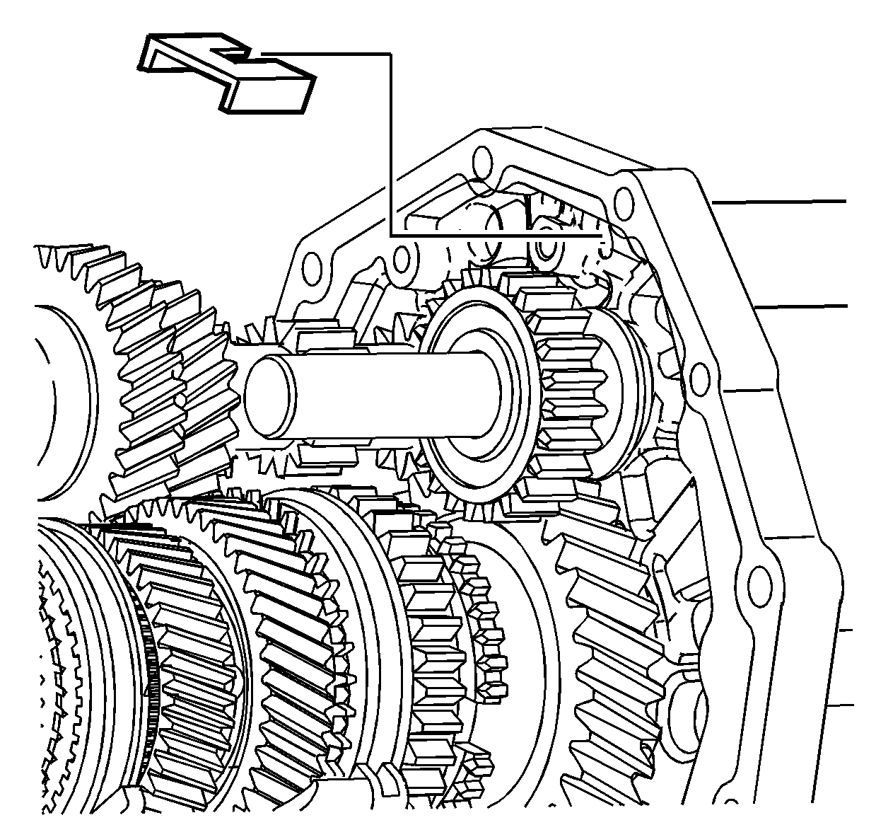
- Remove the magnet.
Notice: Refer to Machined Surface Damage Notice in the Preface section.
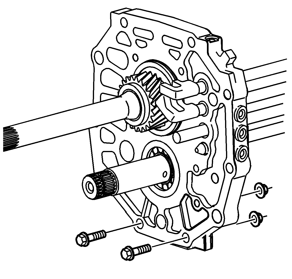
- Install 2 bolts, with nuts, in the lower holes of the intermediate case.
The bolts will be used to hold the intermediate case in a vise during disassembly
and assembly.
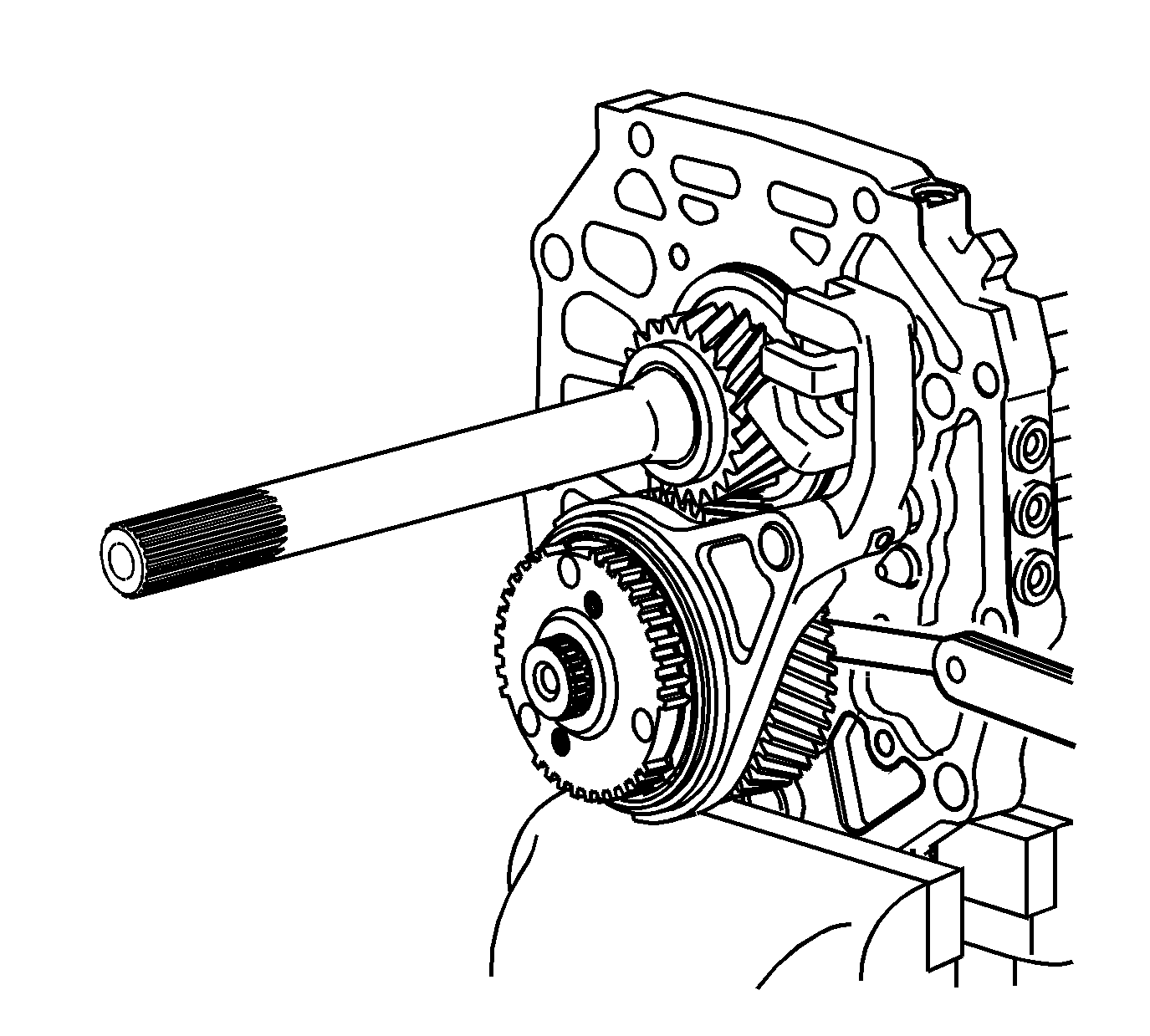
Important: Before removal of the 5th synchronizer gear,
measure the axial play of the speed gear. Incorrect axial play of the gear may cause
shifting concerns or transmission noise.
- Using a feeler gage between the 5th countershaft gear and the thrust washer,
measure the axial clearance.
Specification
| • | Standard Clearance: 0.10-0.35 mm (0.0039-0.0138 in) |
| • | Maximum Clearance: 0.40 mm (0.0157 in) |
- If the clearance exceeds the maximum, refer to
Gears and Shafts Cleaning and Inspection
.
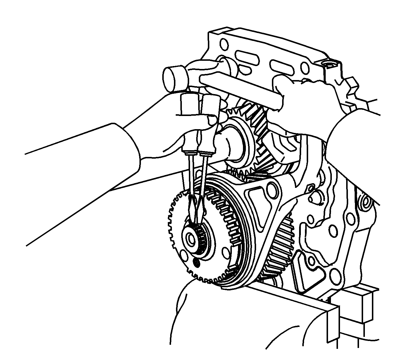
- Mount the intermediate case assembly in a vise on the
2 previously installed bolts.
- Using 2 screwdrivers and a hammer, remove the 5th synchronizer
gear retaining ring.
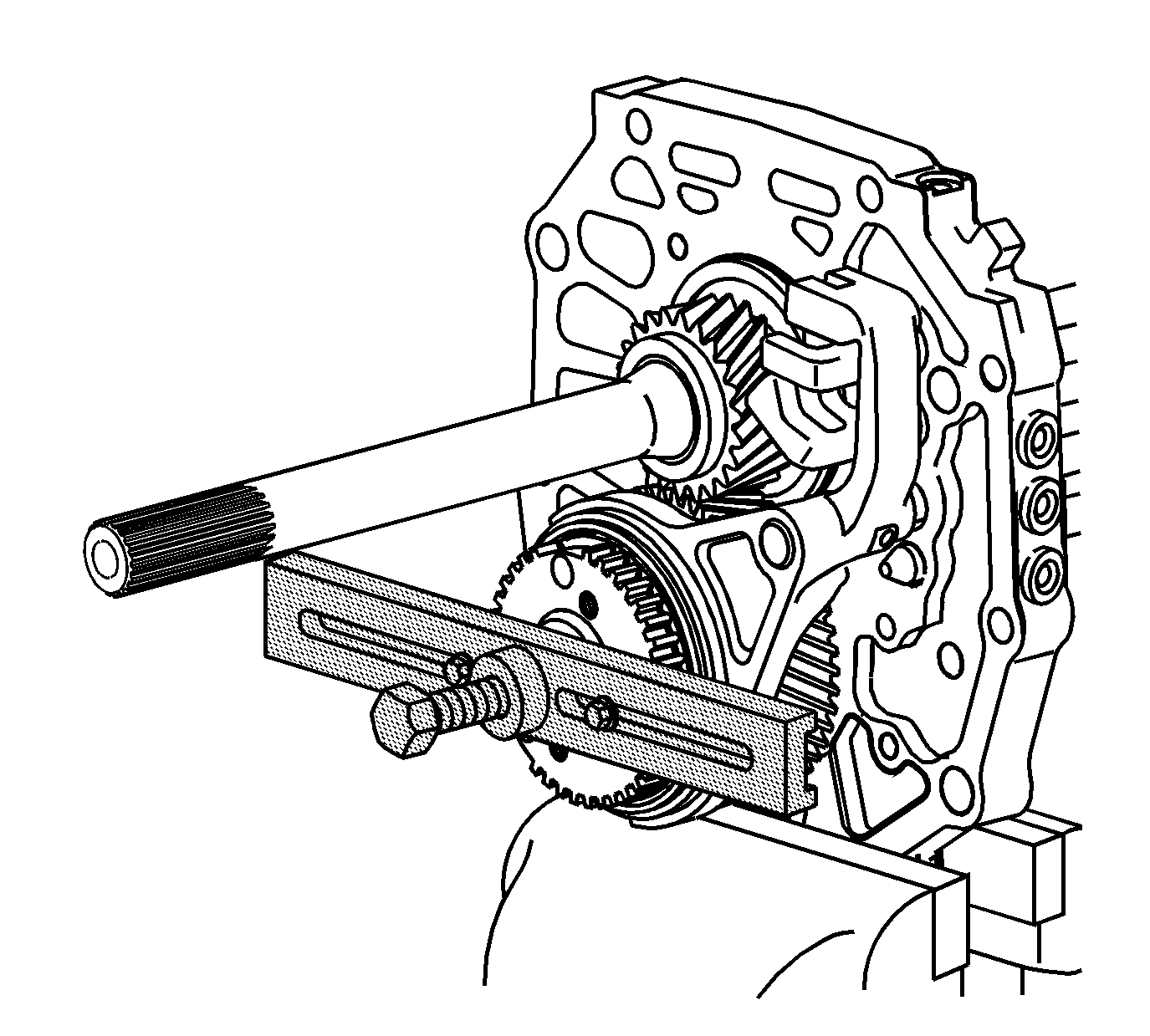
- Using J 8433
with 2 bolts in the threaded holes of the 5th synchronizer gear, remove the
gear.
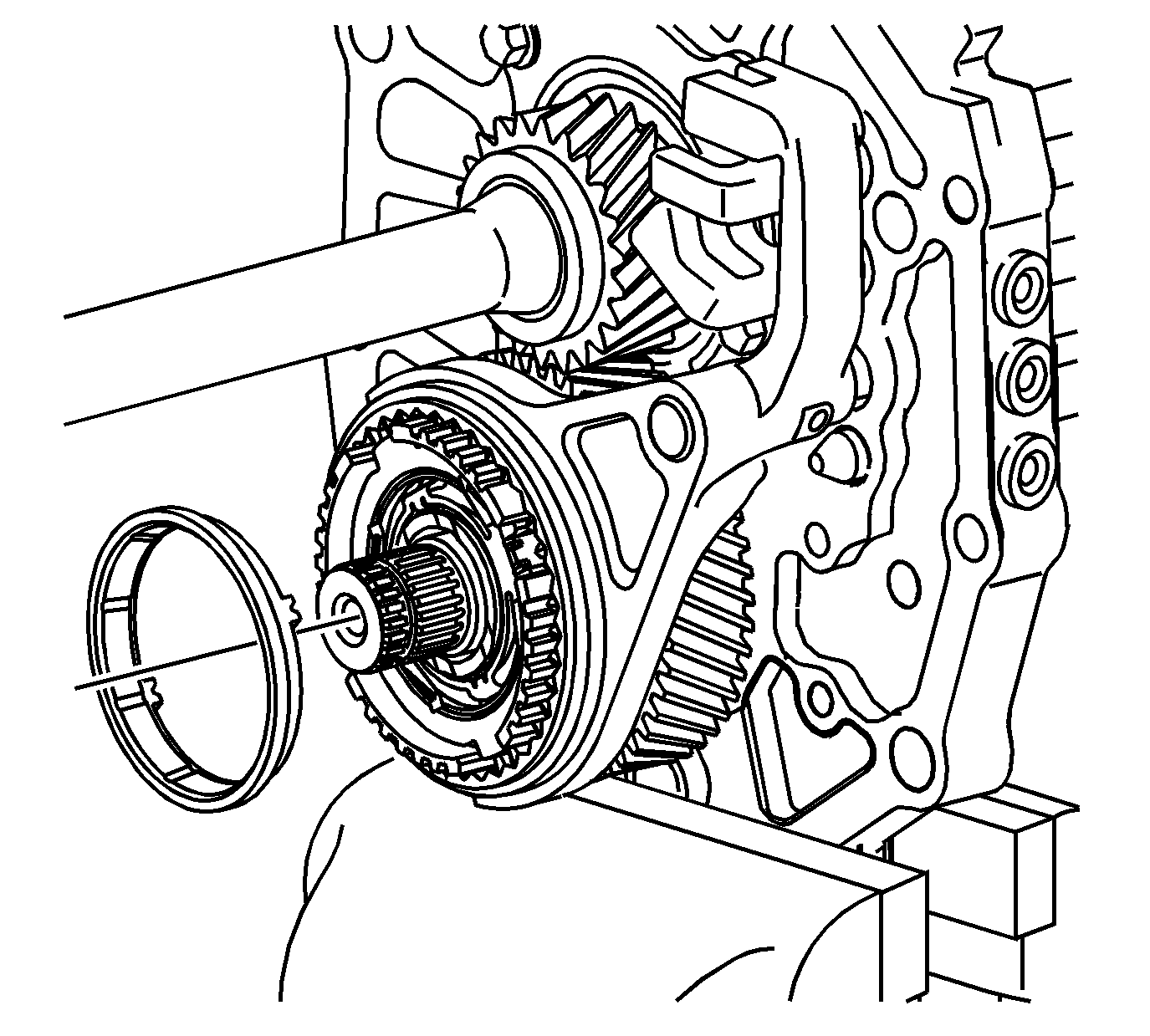
- Remove the 5th/reverse gear synchronizer.
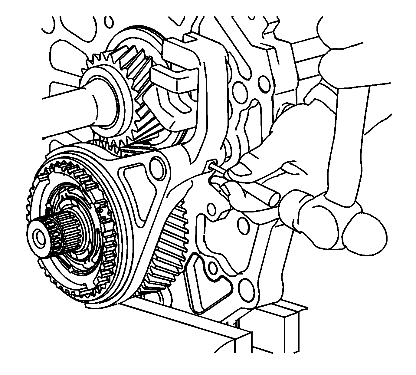
- Using a hammer and a punch, remove the 5th shift fork
roll pin.
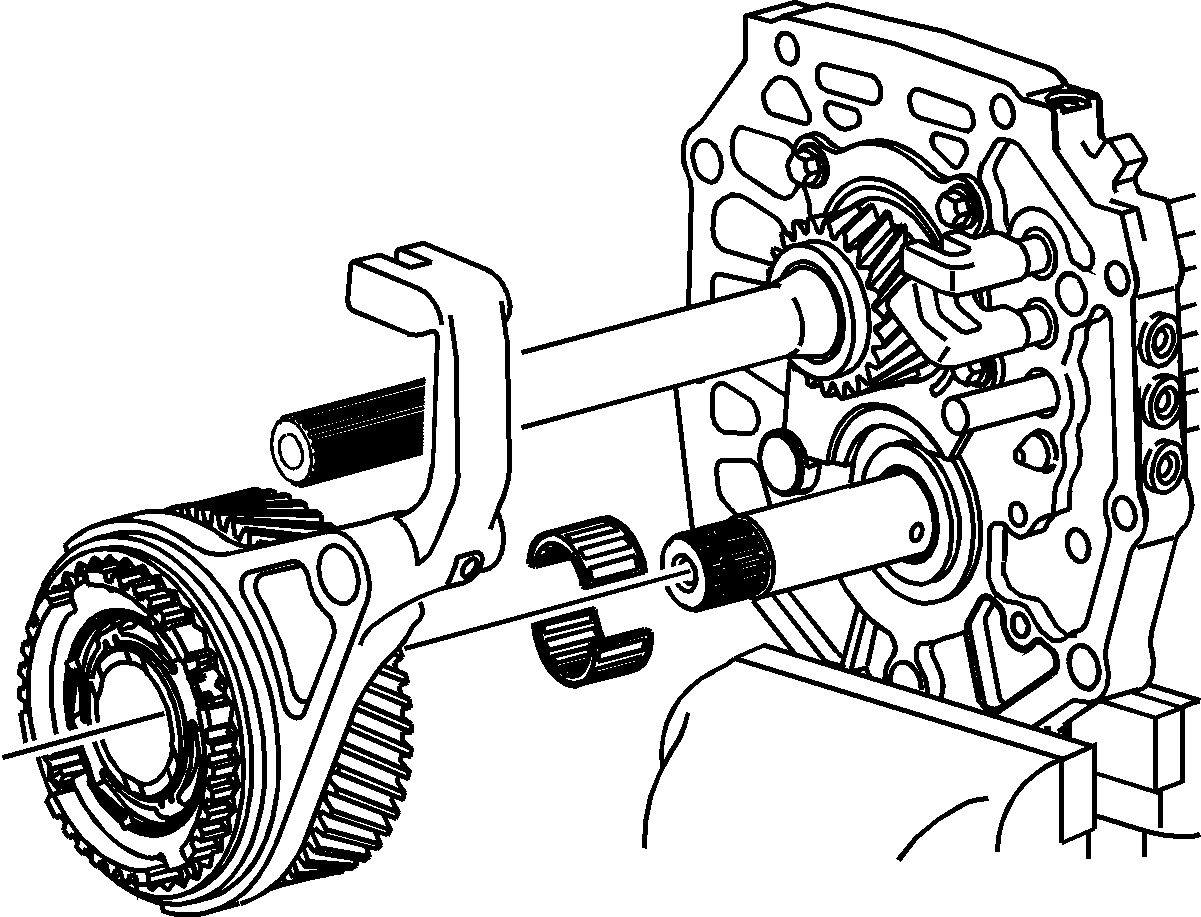
- Remove the shift fork, the 5th/reverse synchronizer
sleeve and blocking ring assembly and the 5th countershaft gear and bearing.
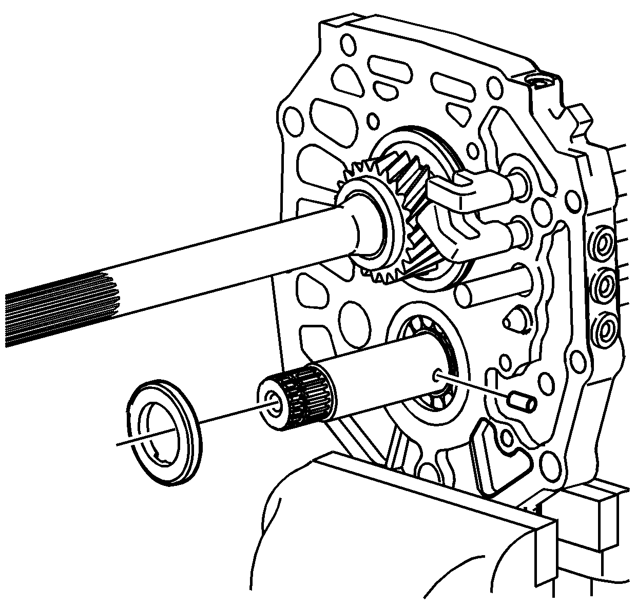
- Remove the 5th countershaft gear thrust washer.
- Remove the thrust washer lock pin.
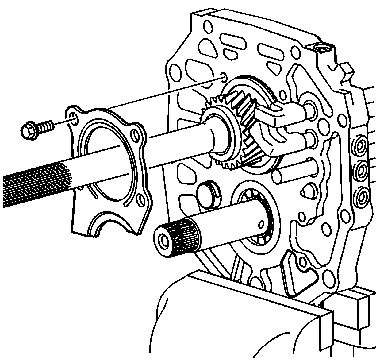
- Remove the bolts for the rear bearing retainer.
- Remove the rear bearing retainer.
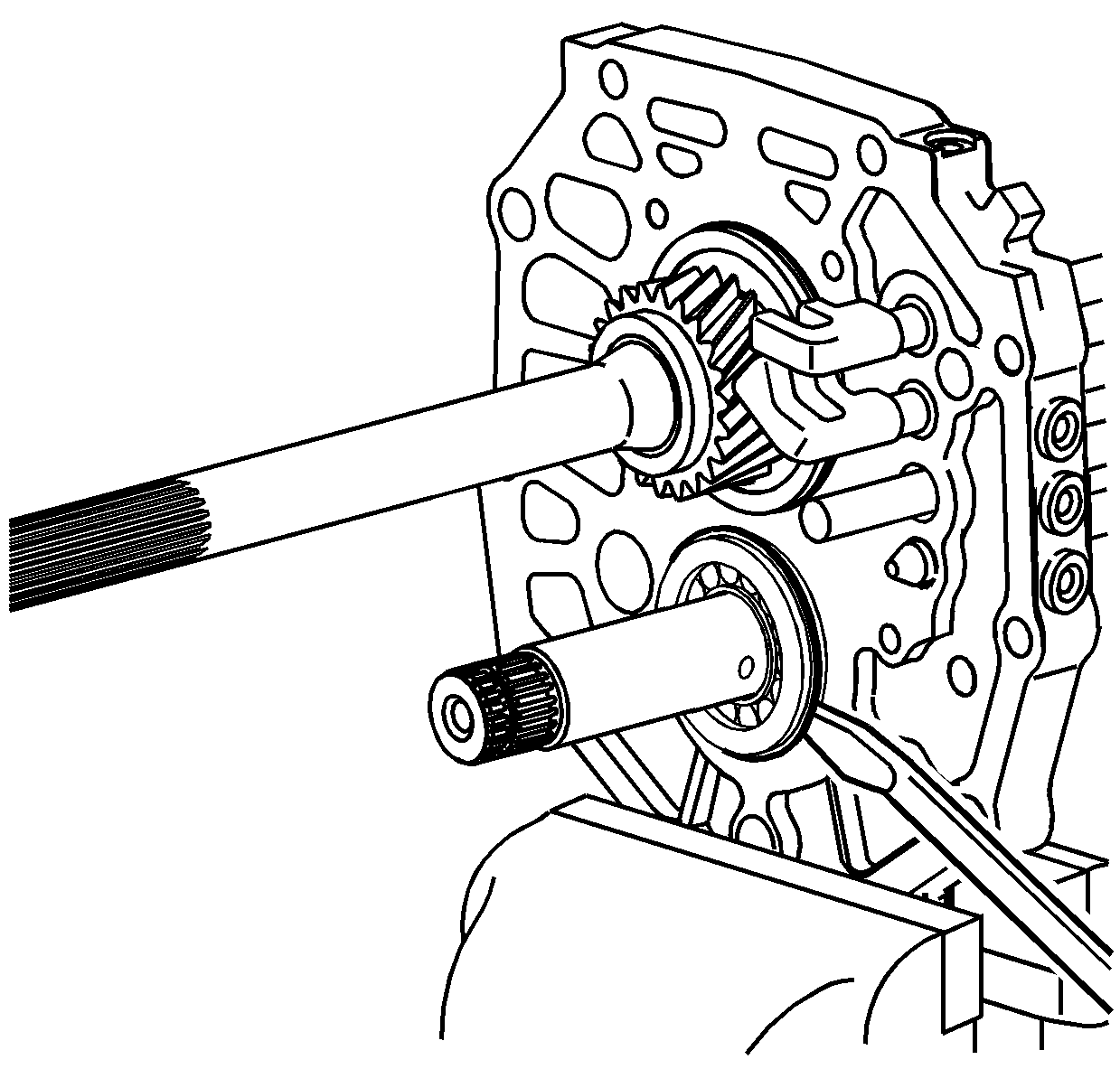
- Using a soft-face hammer, tap the countershaft
rearward to expose the outer retaining ring on the countershaft rear bearing.
- Using a suitable prying tool on the retaining ring, remove the countershaft
rear bearing. The bearing will slide out of the case if the countershaft is kept
in position with the output shaft.
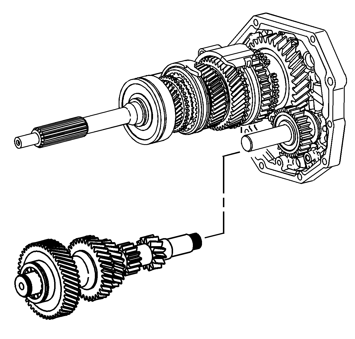
- Remove the countershaft.
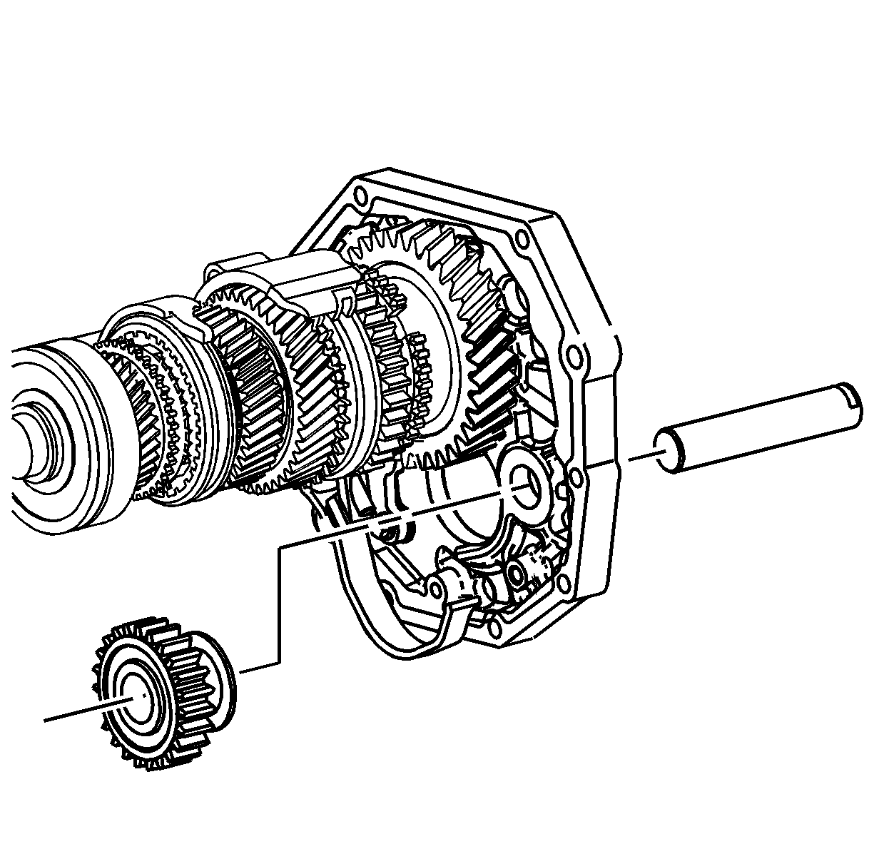
- Remove the reverse idler gear shaft and reverse idler
gear.
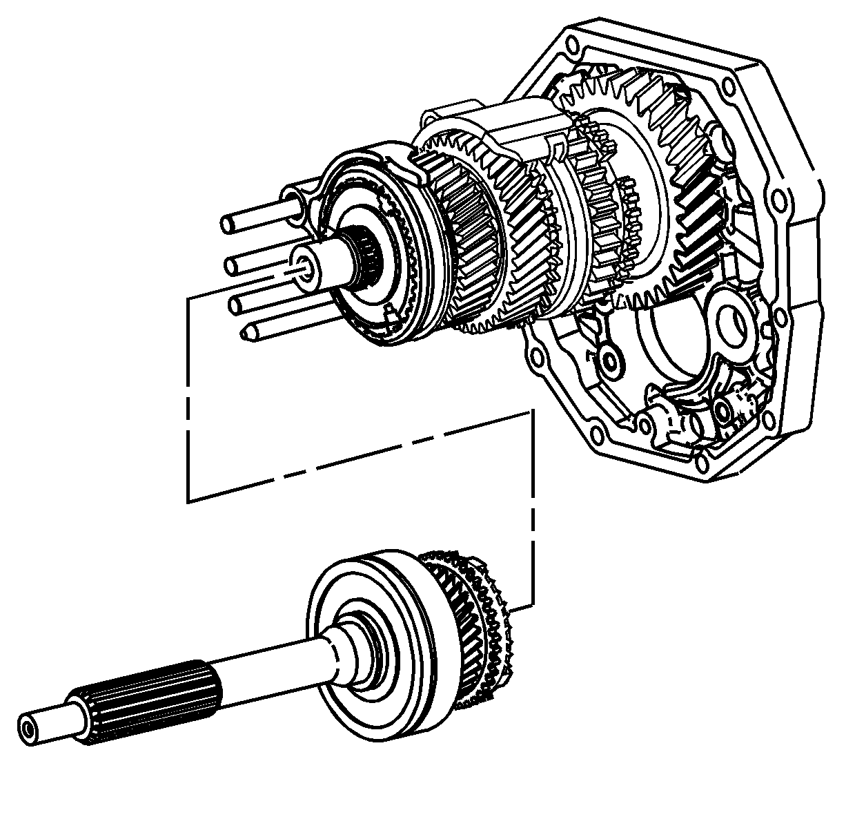
- Remove the input shaft assembly, with the 4th gear
blocking ring, and output shaft front support bearing from the output shaft.
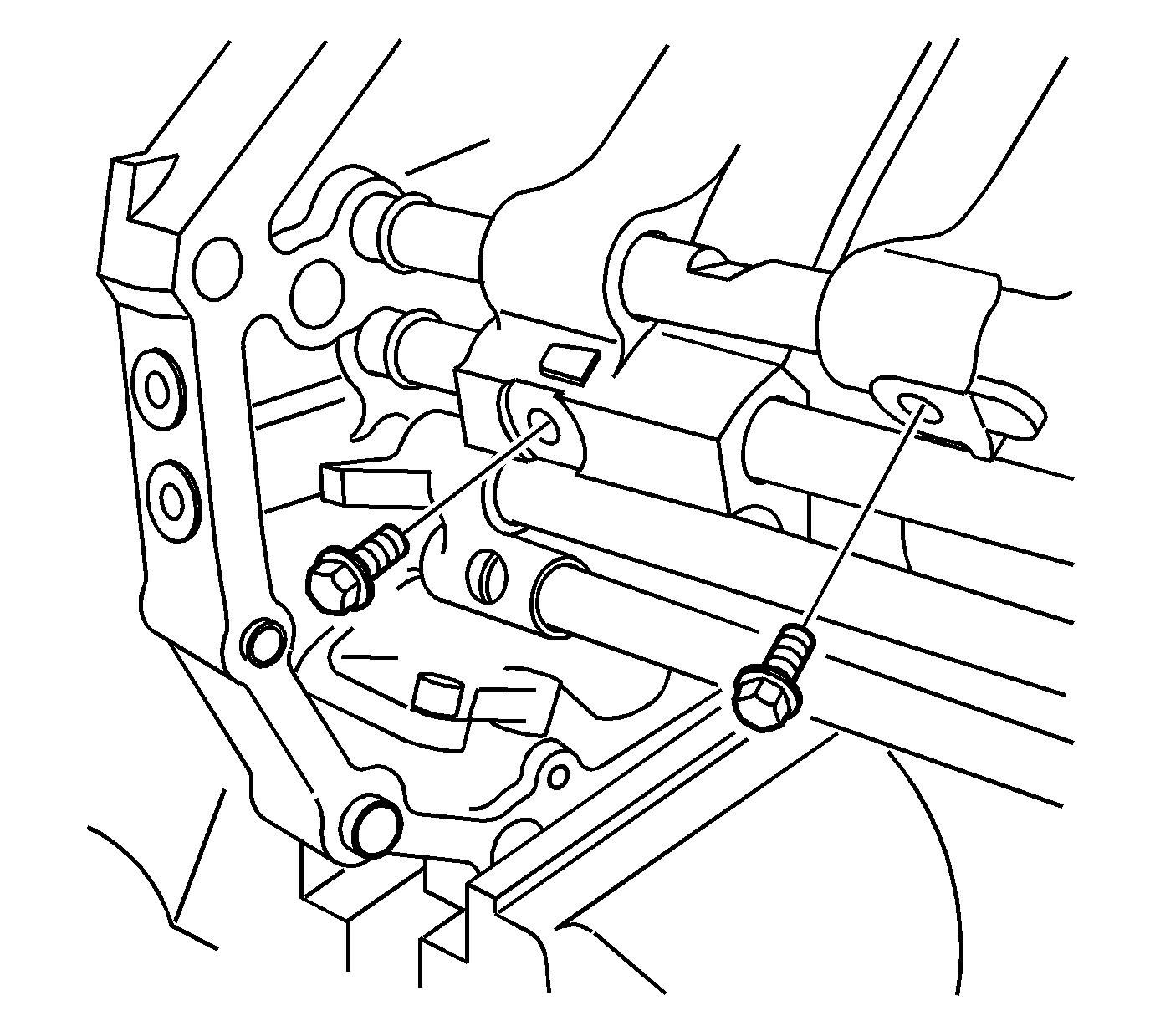
- Remove the 1st/2nd shift fork bolt.
- Remove the 3rd/4th shift fork bolt.
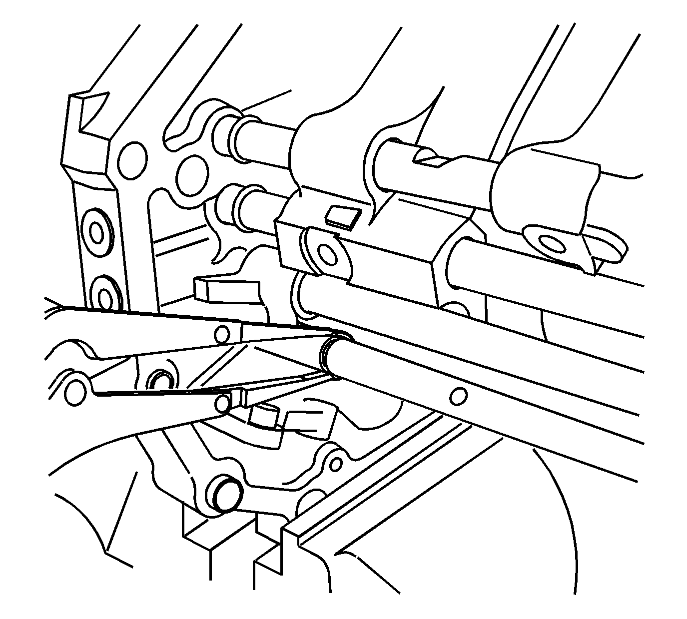
- Remove the retaining ring for the reverse shift lever
on the reverse shift shaft.
| • | Use a suitable pair of pliers to push the retaining ring. |
| • | Only push the retaining ring partially off to keep it from flying. |
| • | Use a pair of pliers to remove the retaining ring the rest of the way. |
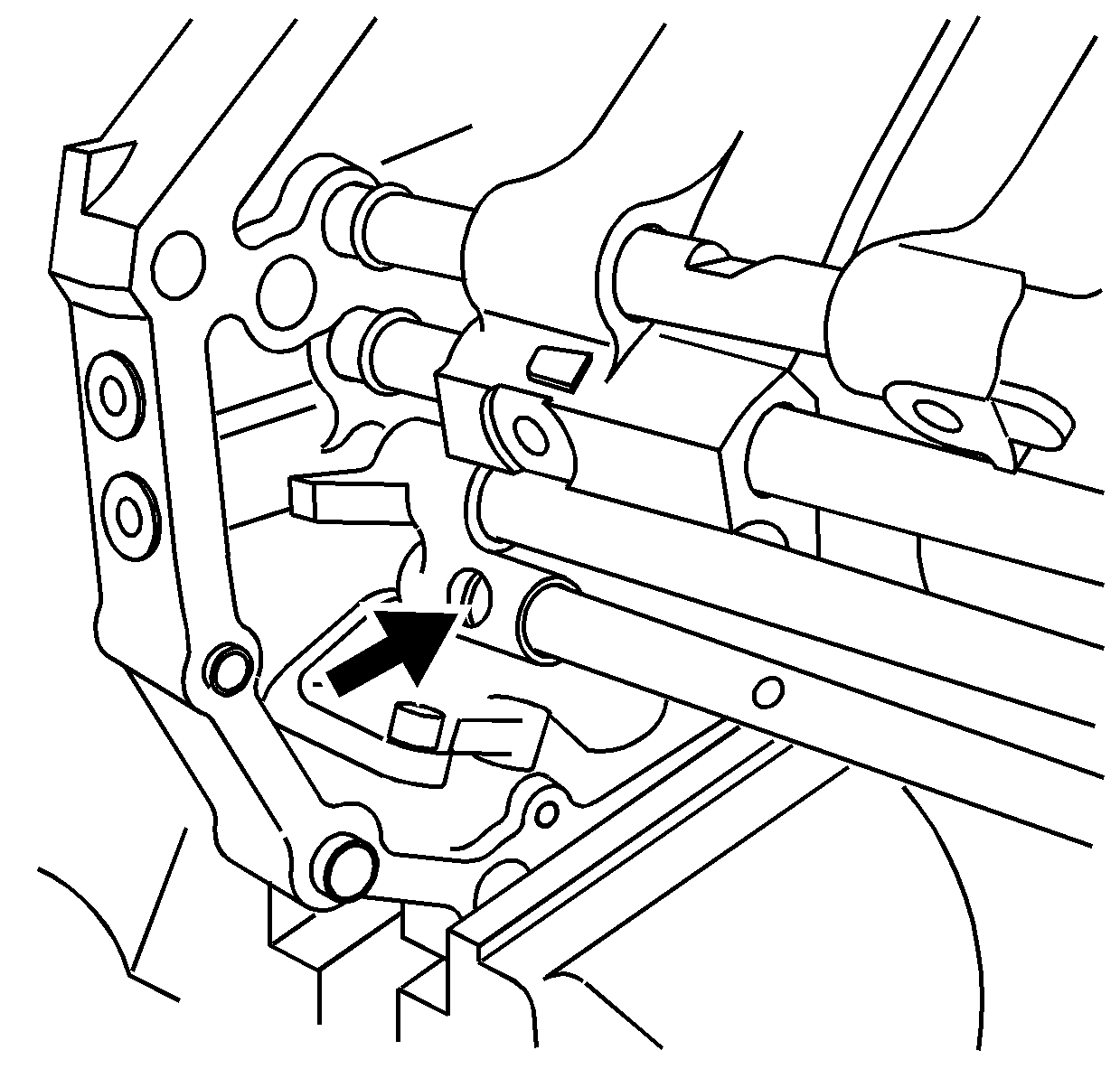
- Shift the reverse shift shaft forward.
- Move the reverse shift lever forward past the retaining ring groove on
the reverse shift shaft. This allows clearance of the reverse shift fork during removal
of the output shaft.
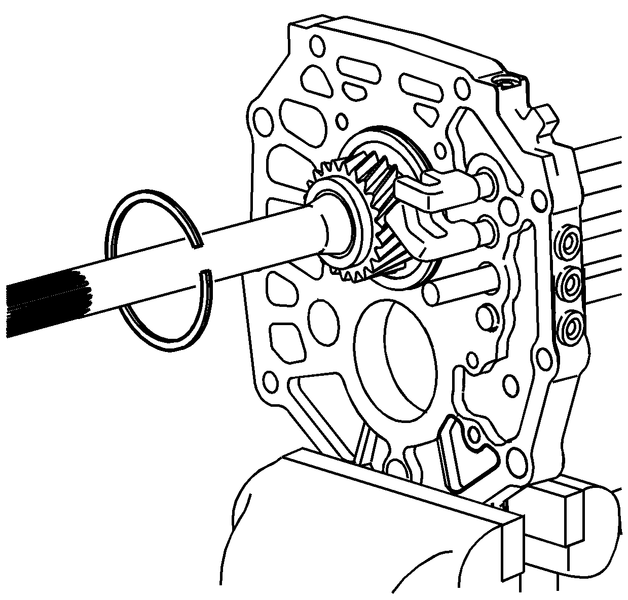
- Remove the output shaft rear bearing outer retaining
ring.
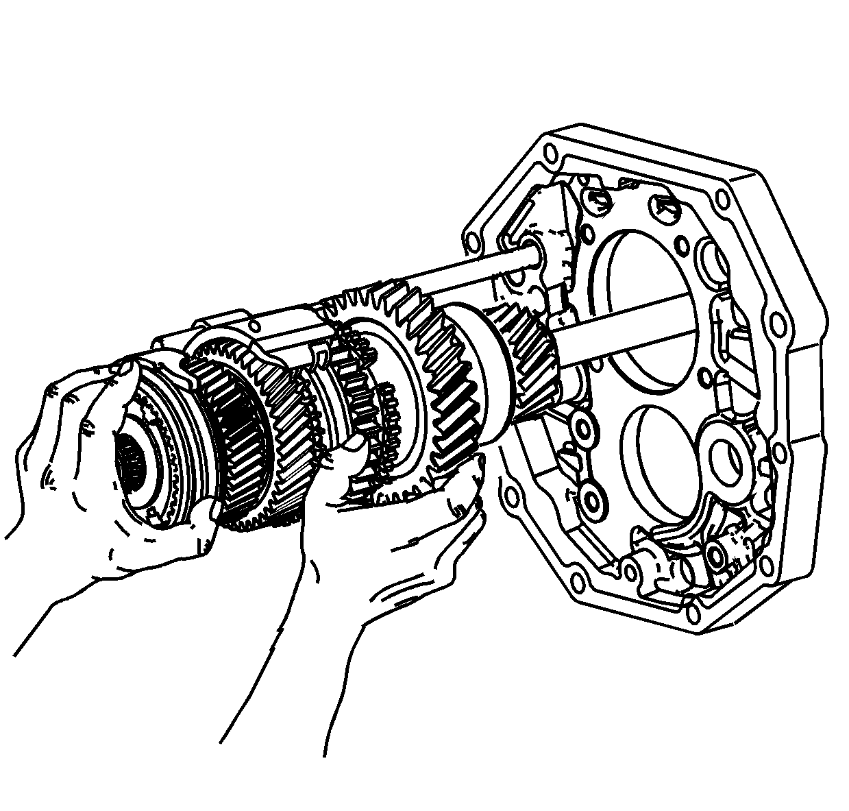
- Remove the output shaft assembly.
| • | Hold the 1st/2nd shift fork and the 3rd/4th shift fork in position to
the output shaft. |
| • | Slide the 1st/2nd shift fork and the 3rd/4th shift fork off the shift
shafts while removing the output shaft. |
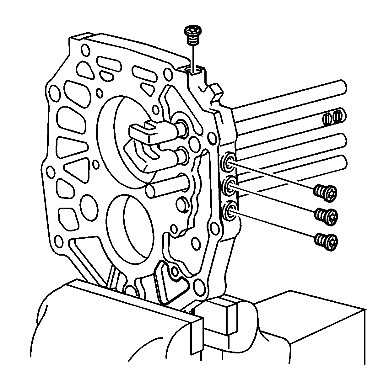
Important: If the shift shafts or the intermediate case
do not require service, proceed to Output Shaft Disassemble. If the shift shafts
or intermediate case require service, proceed to the next step.
- Remove the 4 shift shaft detent plugs for the shift detent balls and
springs. Discard the plugs. New plugs are required for assembly.
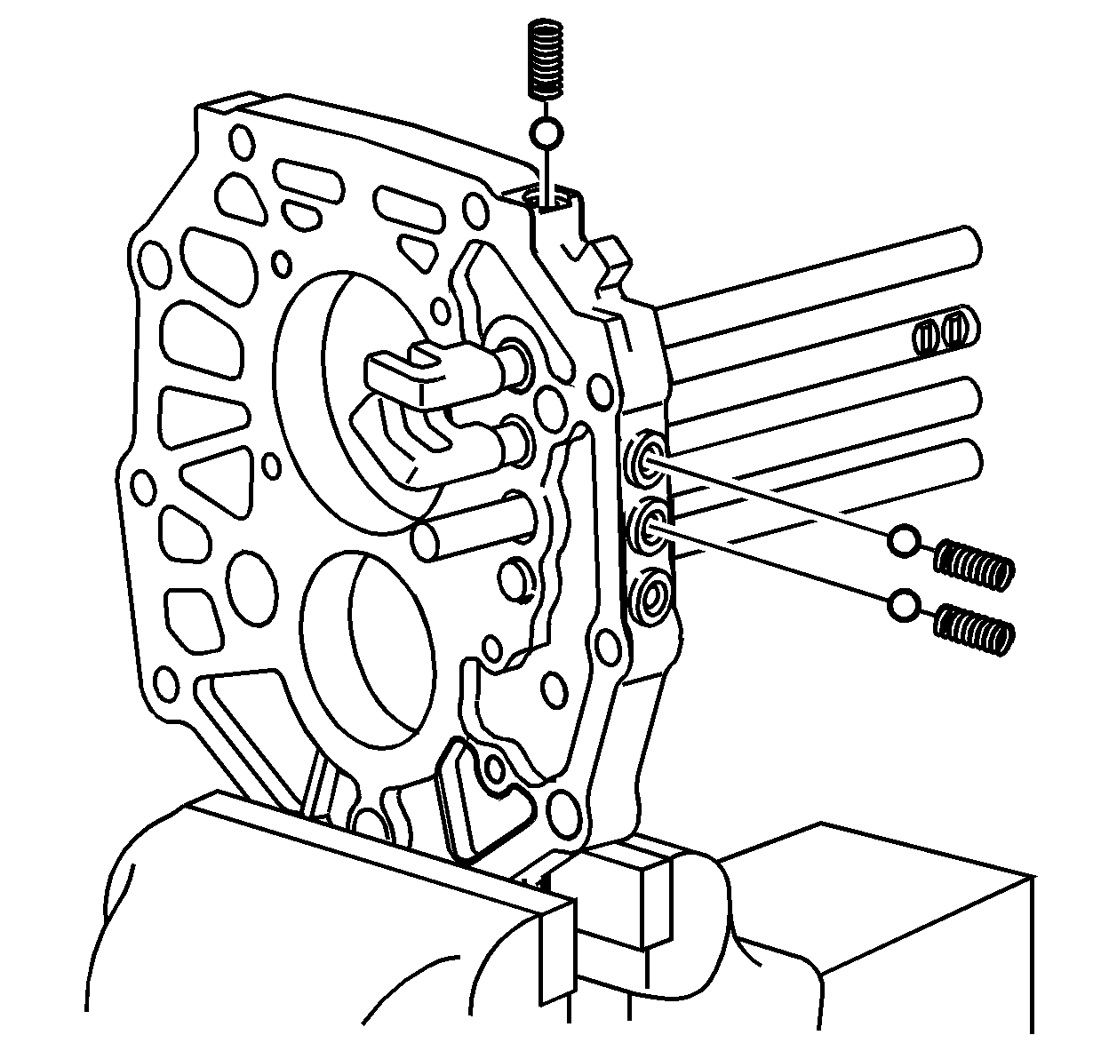
- Using a magnet, remove the 1st/2nd shift shaft detent
spring and ball.
- Using a magnet, remove the 3rd/4th shift shaft detent spring and ball.
- Using a magnet, remove the 5th shift shaft detent spring and ball. The
reverse shift shaft does not have a detent spring and ball in the plug opening.
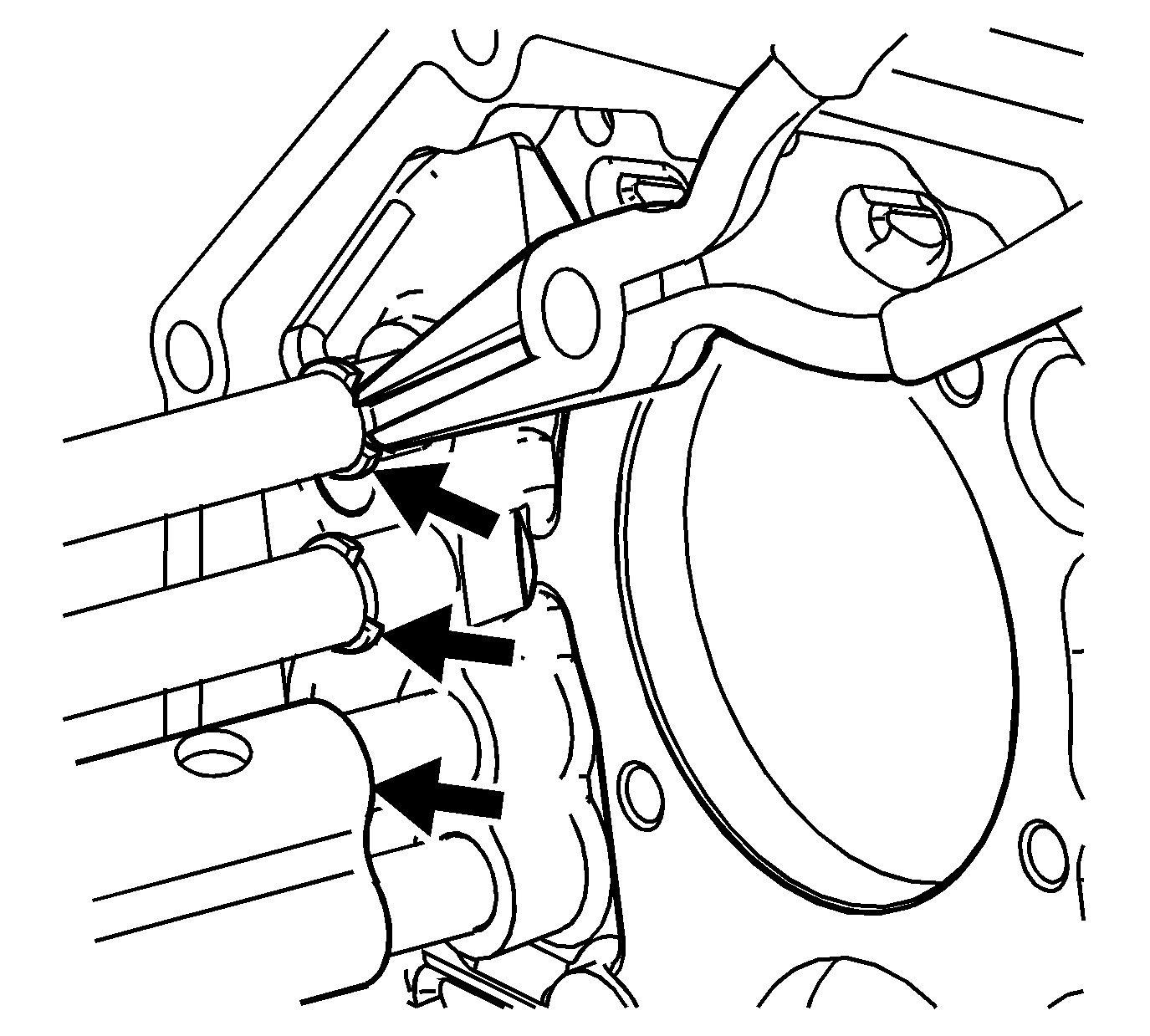
Important: To prevent the retaining rings from flying,
cover the area with a rag.
- Remove the following shift shaft retaining rings:
| • | The 1st/2nd shift shaft |
| • | The 3rd/4th shift shaft |
| - | Use a suitable pair of pliers to push the retaining ring. |
| - | Only push the retaining ring partially off to keep it from flying. |
| - | Use a pair of pliers to remove the retaining ring the rest of the way. |
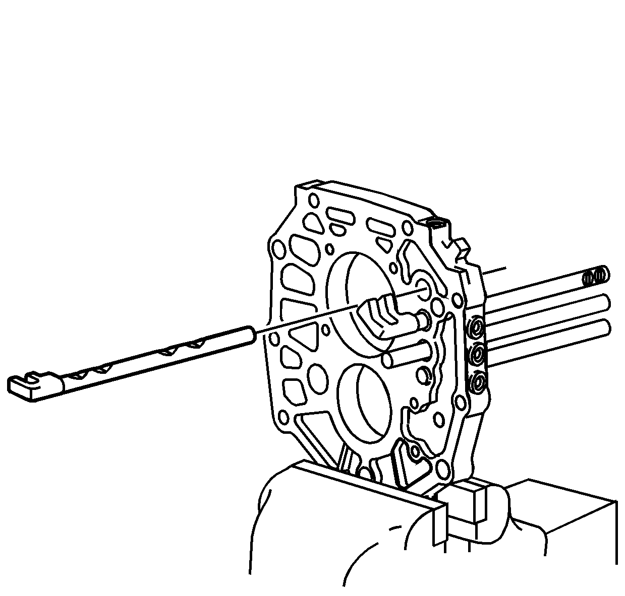
- Remove the 3rd/4th shift shaft.
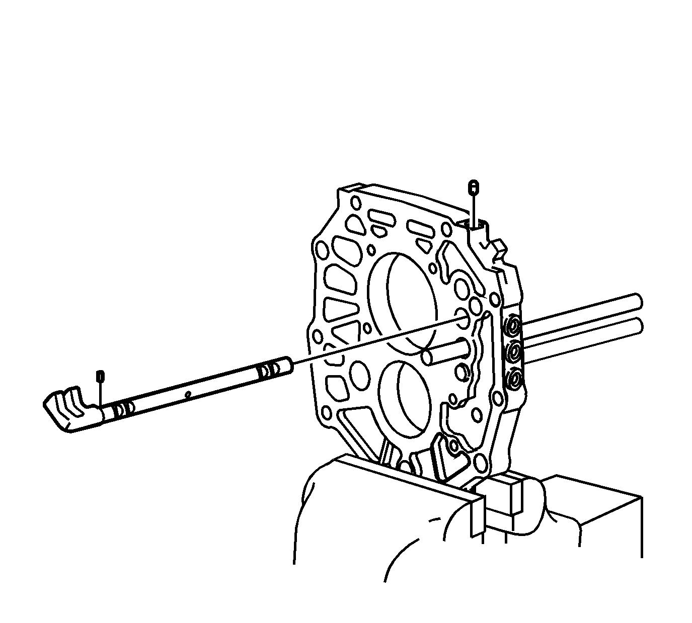
- Using a magnet, remove the 1st/2nd and 3rd/4th shift
shaft interlock pin.
- Remove the 1st/2nd shift shaft.
- Remove the small interlock pin from the 1st/2nd shift shaft.
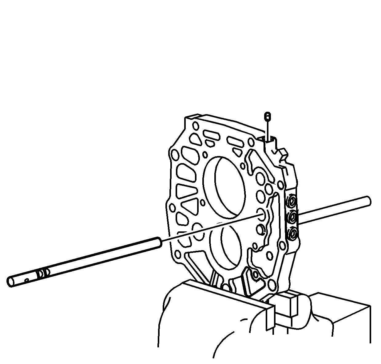
- Using a magnet, remove the 5th shift shaft and 1st/2nd
shift shaft interlock pin.
- Remove the 5th shift shaft.
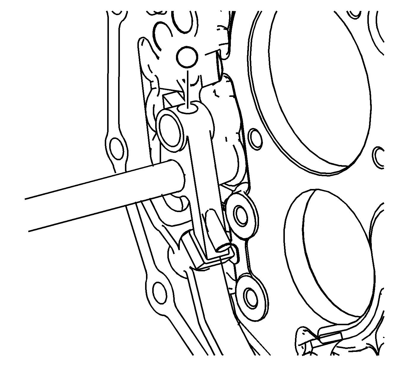
- Remove the detent ball from the reverse shift lever.
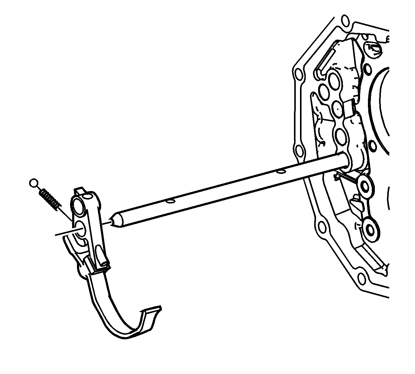
- Remove the reverse shift lever, with the reverse shift
fork, from the reverse shift shaft.
| 64.1. | Slide the shift lever to the end of the shaft. |
| 64.2. | Cover the detent ball opening with your hand. |
| 64.3. | Let the detent ball and spring land in your hand. |
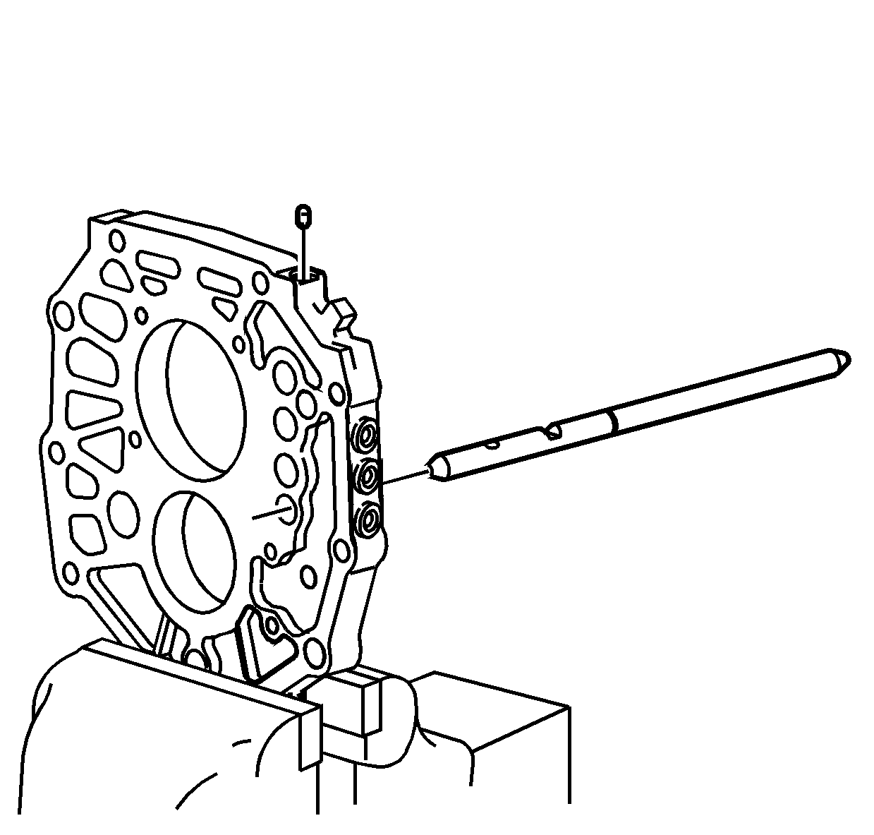
- Using a magnet, remove the interlock pin from the reverse
shift shaft. The shaft may require moving back and forth to remove the interlock pin.
- Remove the reverse shift shaft.
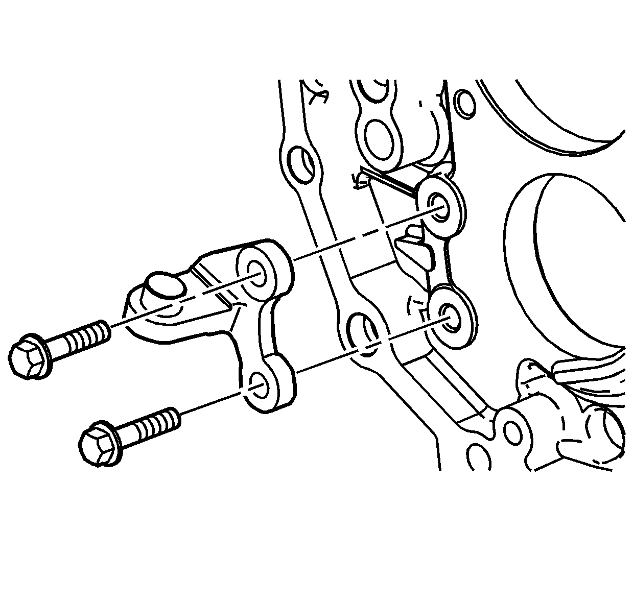
- Remove the bolts and the reverse shift fork bracket.
Transmission Disassemble Colorado
Tools Required
J 8433
Two Jaw Puller

Important: The following steps apply to both the 4WD and the RWD transmission, except where noted.
- Remove the drain plug, with aluminum washer, and drain the transmission fluid.

- If RWD, remove the vehicle speed sensor with O-ring
seal.

- Remove the backup lamp switch, with the aluminum washer, from the front case.

- Remove the 9 bolts retaining the clutch housing.
- Using a soft-face hammer, remove the clutch housing from the transmission assembly.

- Shift the transmission into NEUTRAL.
- Remove the shift control housing bolts.
- Remove the shift control housing.
- Remove the shift control housing gasket.

- Remove the shift control lever socket bolt.

- Mark the location of the brackets and the studs.
- Remove the extension housing retaining bolts, studs, and brackets.
The 4WD does not use a bracket on the left side of the transmission.
Notice: Refer to Machined Surface Damage Notice in the Preface section.

- Using a soft-face hammer, separate the extension housing from the intermediate case.
- Slide the extension housing off the shift control shaft.
- Remove the shift control socket from the extension housing shift lever cavity.

- Remove the shift control shaft from the shift shaft gates.

- Remove the front bearing retainer bolts. Discard the bolts. New bolts are required
for assembly.
- Remove the front bearing retainer.

- Using a suitable punch and a hammer, remove the input shaft seal from the bearing
retainer. Do not use the seal again.

- Remove the outer retaining ring from the input shaft bearing.
- Remove the outer retaining ring from the countershaft front bearing.
Notice: Refer to Machined Surface Damage Notice in the Preface section.

- Using a soft-face hammer on the transmission front case, shear the sealer.
- Remove the transmission front case from the intermediate case.

- Remove the oil baffle bolts.
- Remove the oil baffle.

- Remove the magnet.
Notice: Refer to Machined Surface Damage Notice in the Preface section.

- Install 2 bolts, with nuts, in the lower holes of the intermediate case. The bolts will be used to hold the intermediate case in a vise during disassembly and assembly.

Important: Before removal of the 5th synchronizer gear, measure the axial play of the speed gear. Incorrect axial play of the gear may cause shifting concerns or transmission noise.
- Using a feeler gage between the 5th countershaft gear and the thrust washer, measure the axial clearance.
Specification
| • | Standard Clearance: 0.10-0.35 mm (0.0039-0.0138 in) |
| • | Maximum Clearance: 0.40 mm (0.0157 in) |
- If the clearance exceeds the maximum, refer to
Gears and Shafts Cleaning and Inspection
.

- Mount the intermediate case assembly in a vise on the 2 previously installed
bolts.
- Using 2 screwdrivers and a hammer, remove the 5th synchronizer gear retaining ring.

- Using
J 8433
with 2 bolts in the threaded holes
of the 5th synchronizer gear, remove the gear.

- Remove the 5th/reverse gear synchronizer.

- Using a hammer and a punch, remove the 5th shift fork roll pin.

- Remove the shift fork, the 5th/reverse synchronizer sleeve and blocking ring assembly and the 5th countershaft
gear and bearing.

- Remove the 5th countershaft gear thrust
washer.
- Remove the thrust washer lock pin.

- Remove the bolts for the rear bearing retainer.
- Remove the rear bearing retainer.

- Using a soft-face hammer, tap the countershaft rearward to expose the outer
retaining ring on the countershaft rear bearing.
- Using a suitable prying tool on the retaining ring, remove the countershaft rear bearing. The bearing will slide out of the case if the countershaft is kept in position with the output shaft.

- Remove the countershaft.

- Remove the reverse idler gear shaft
and reverse idler gear.

- Remove the input shaft assembly, with
the 4th gear blocking ring, and output shaft front support bearing from the output shaft.

- Remove the 1st/2nd shift fork bolt.
- Remove the 3rd/4th shift fork bolt.

- Remove the retaining ring for the reverse
shift lever on the reverse shift shaft.
| • | Use a suitable pair of pliers to push the retaining ring. |
| • | Only push the retaining ring partially off to keep it from flying. |
| • | Use a pair of pliers to remove the retaining ring the rest of the way. |

- Shift the reverse shift shaft forward.
- Move the reverse shift lever forward past the retaining ring groove on the reverse shift shaft. This allows clearance of the reverse shift fork during removal of the output shaft.

- Remove the output shaft rear bearing
outer retaining ring.

- Remove the output shaft assembly.
| • | Hold the 1st/2nd shift fork and the 3rd/4th shift fork in position to the output shaft. |
| • | Slide the 1st/2nd shift fork and the 3rd/4th shift fork off the shift shafts while removing the output shaft. |

Important: If the shift shafts or the intermediate case do not require service, proceed to Output Shaft Disassemble. If the shift shafts or intermediate case require service, proceed to the next step.
- Remove the 4 shift shaft detent plugs for the shift detent balls and springs. Discard the plugs. New plugs are required for assembly.

- Using a magnet, remove the 1st/2nd shift shaft detent spring and ball.
- Using a magnet, remove the 3rd/4th shift shaft detent spring and ball.
- Using a magnet, remove the 5th shift shaft detent spring and ball. The reverse shift shaft does not have a detent spring and ball in the plug opening.

Important: To prevent the retaining rings from flying, cover the area with a rag.
- Remove the following shift shaft retaining rings:
| • | The 1st/2nd shift shaft |
| • | The 3rd/4th shift shaft |
| - | Use a suitable pair of pliers to push the retaining ring. |
| - | Only push the retaining ring partially off to keep it from flying. |
| - | Use a pair of pliers to remove the retaining ring the rest of the way. |

- Remove the 3rd/4th shift shaft.

- Using a magnet, remove the 1st/2nd and 3rd/4th shift shaft interlock pin.
- Remove the 1st/2nd shift shaft.
- Remove the small interlock pin from the 1st/2nd shift shaft.

- Using a magnet, remove the 5th shift shaft and 1st/2nd shift shaft interlock pin.
- Remove the 5th shift shaft.

- Remove the detent ball from the reverse shift lever.

- Remove the reverse shift lever, with
the reverse shift fork, from the reverse shift shaft.
| 64.1. | Slide the shift lever to the end of the shaft. |
| 64.2. | Cover the detent ball opening with your hand. |
| 64.3. | Let the detent ball and spring land in your hand. |

- Using a magnet, remove the interlock pin from the reverse shift shaft. The shaft may require moving back and
forth to remove the interlock pin.
- Remove the reverse shift shaft.

- Remove the bolts and the reverse shift fork bracket.
Transmission Disassemble Solstice
Tools Required
J 8433
Two Jaw Puller

- Remove the drain plug, with aluminum washer, and drain the transmission fluid.
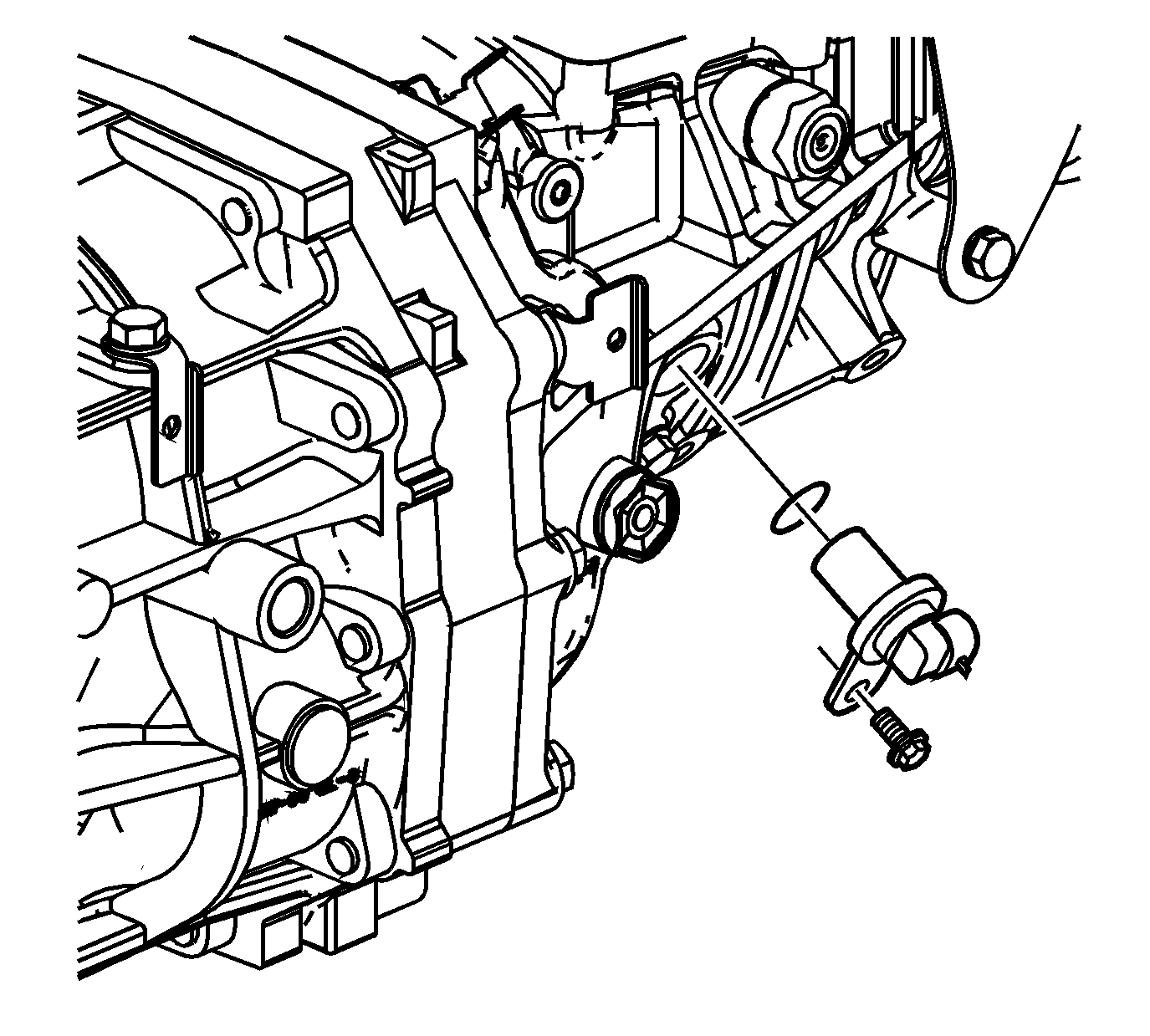
- Remove the vehicle speed sensor with O-ring seal.
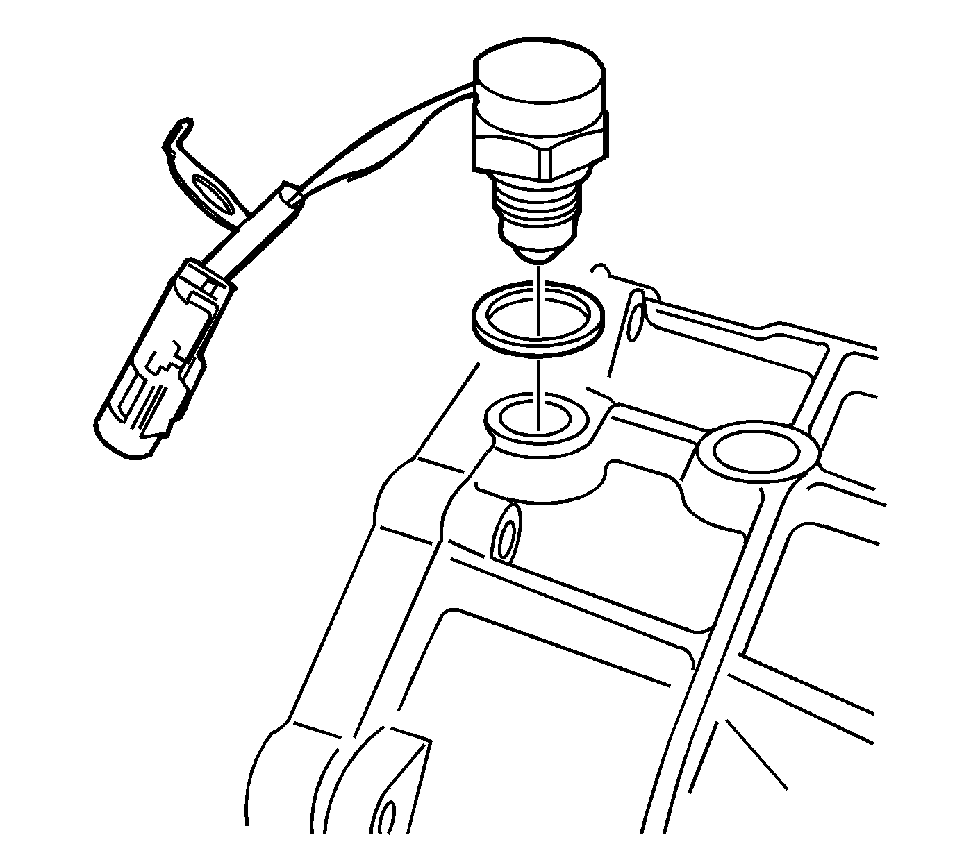
- Remove the backup lamp switch, with the aluminum washer, from the front case.
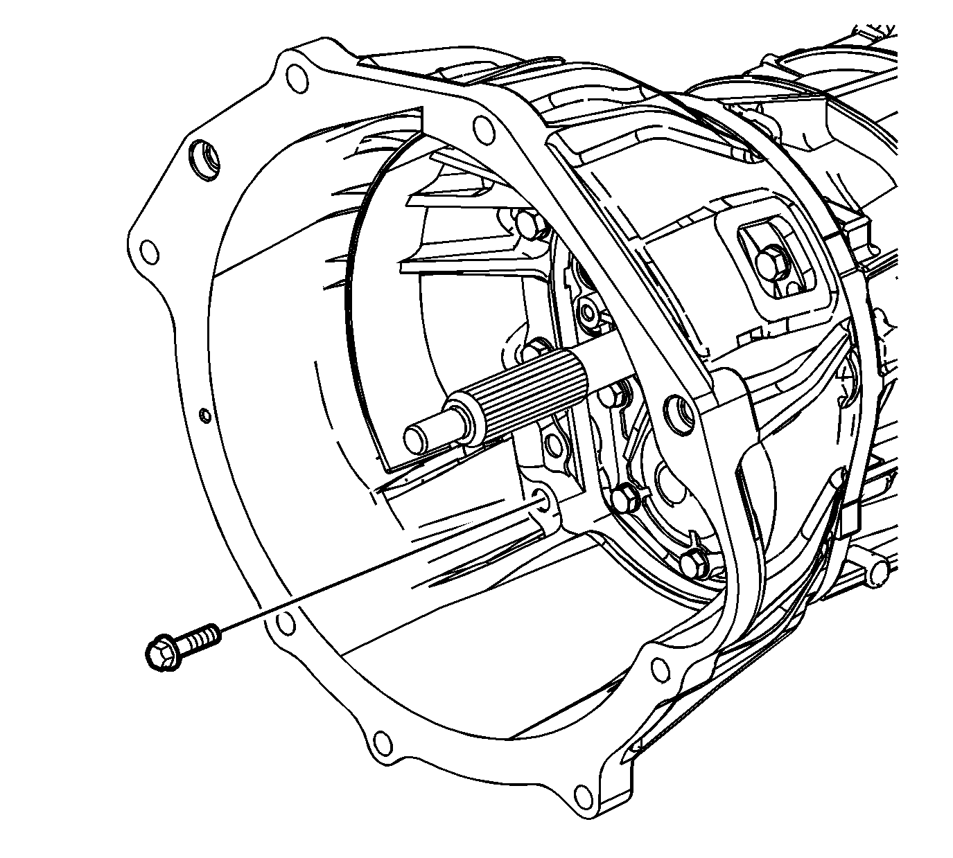
- Remove the 9 bolts retaining the clutch housing.
- Using a soft-face hammer, remove the clutch housing from the transmission assembly.
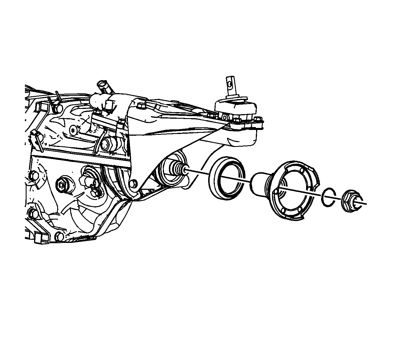
- Remove the output shaft nut.
- Remove the o-ring seal.
- Remove the output flange.
- Remove the output flange dirt deflector.
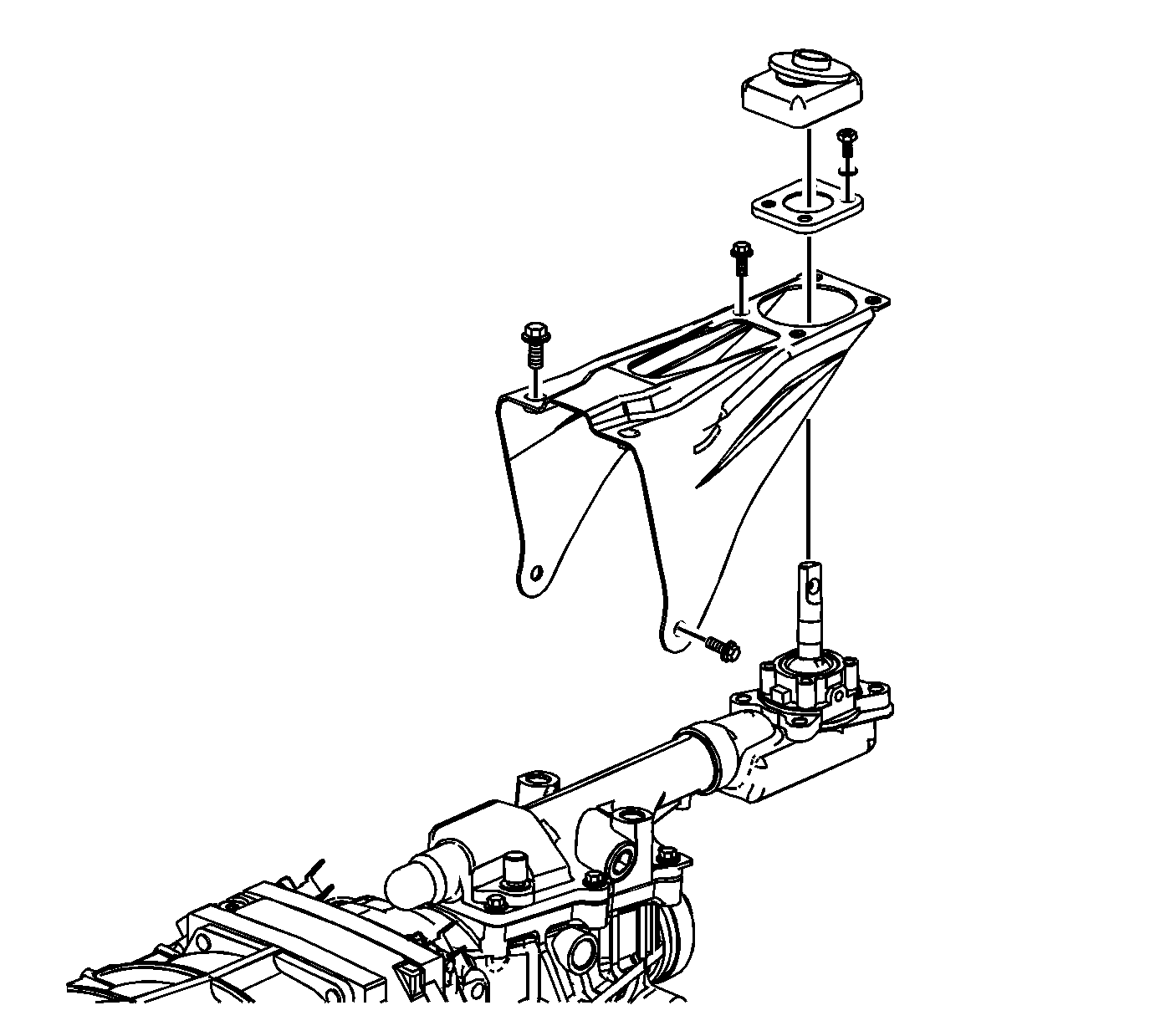
- Remove the shift control lever boot.
- Remove the shift control lever bolt/screw and retainer.
- Remove the shift control bracket screws and shift control bracket.
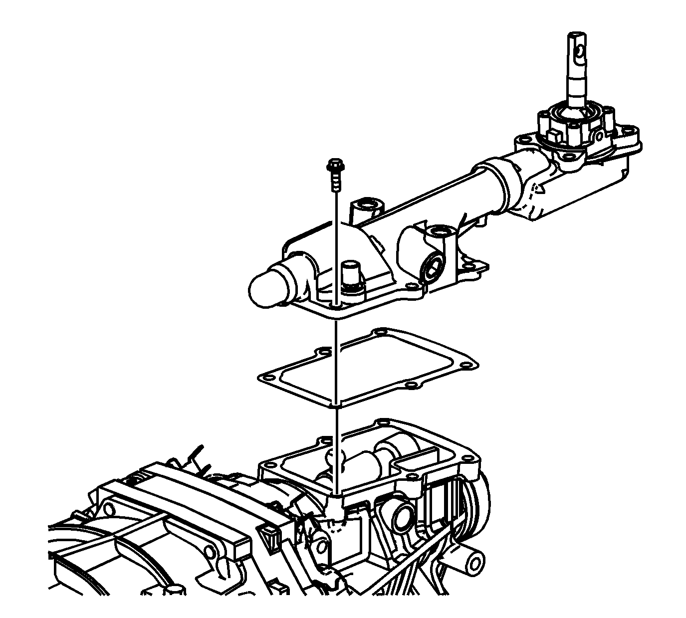
- Shift the transmission into NEUTRAL.
- Remove the shift control housing bolts.
- Remove the shift control housing.
- Remove the shift control housing gasket.
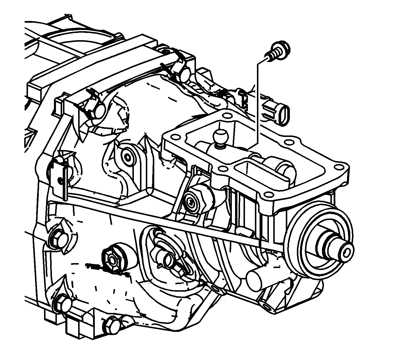
- Remove the shift control lever socket bolt.
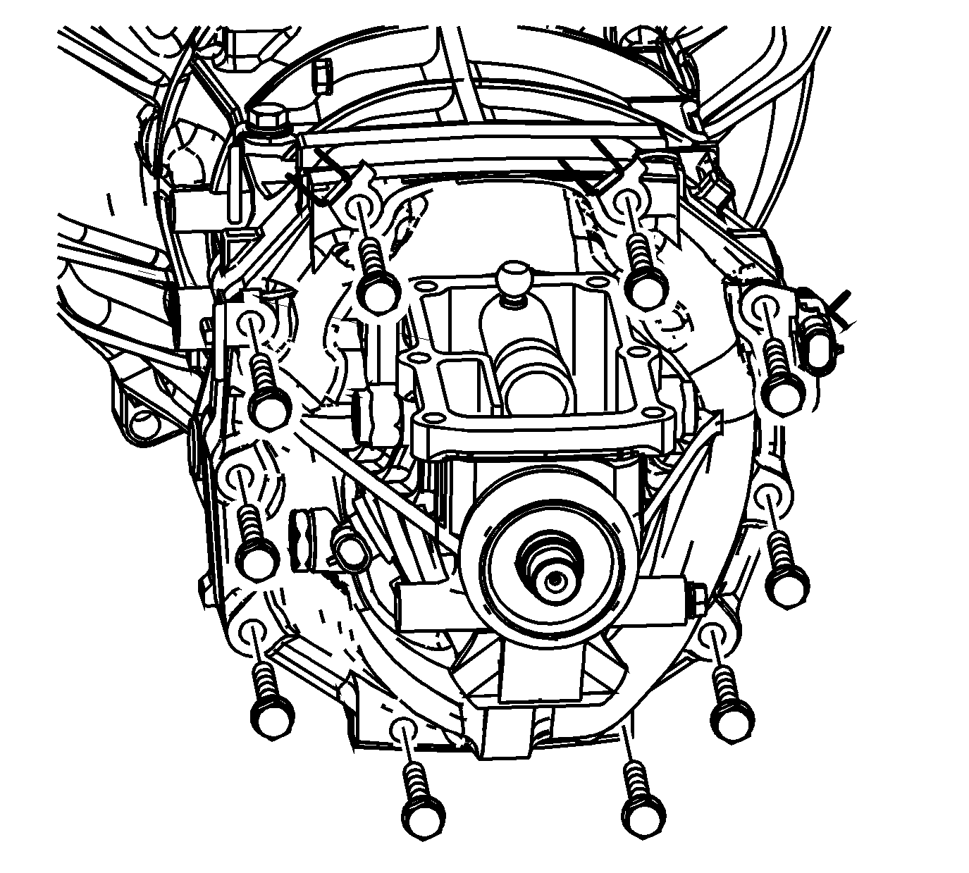
- Mark the location of the brackets and the studs.
- Remove the extension housing retaining bolts, studs, and brackets.
Notice: Refer to Machined Surface Damage Notice in the Preface section.
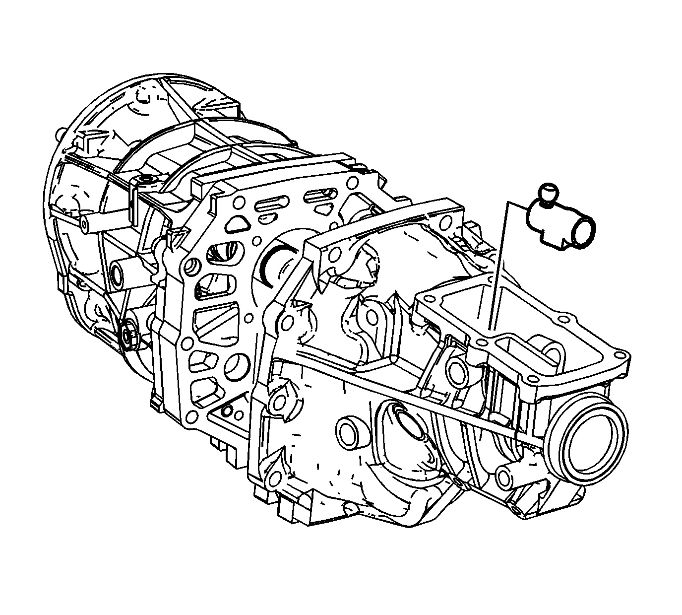
- Using a soft-face hammer, separate the extension housing from the intermediate case.
- Slide the extension housing off the shift control shaft.
- Remove the shift control socket from the extension housing shift lever cavity.

- Remove the shift control shaft from the shift shaft gates.

- Remove the front bearing retainer bolts. Discard the bolts. New bolts are required
for assembly.
- Remove the front bearing retainer.

- Using a suitable punch and a hammer, remove the input shaft seal from the bearing
retainer. Do not use the seal again.

- Remove the outer retaining ring from the input shaft bearing.
- Remove the outer retaining ring from the countershaft front bearing.
Notice: Refer to Machined Surface Damage Notice in the Preface section.

- Using a soft-face hammer on the transmission front case, shear the sealer.
- Remove the transmission front case from the intermediate case.

- Remove the oil baffle bolts.
- Remove the oil baffle.

- Remove the magnet.
Notice: Refer to Machined Surface Damage Notice in the Preface section.

- Install 2 bolts, with nuts, in the lower holes of the intermediate case. The bolts will be used to hold the intermediate case in a vise during disassembly and assembly.

Important: Before removal of the 5th synchronizer gear, measure the axial play of the speed gear. Incorrect axial play of the gear may cause shifting concerns or transmission noise.
- Using a feeler gage between the 5th countershaft gear and the thrust washer, measure the axial clearance.
Specification
| • | Standard Clearance: 0.10-0.35 mm (0.0039-0.0138 in) |
| • | Maximum Clearance: 0.40 mm (0.0157 in) |
- If the clearance exceeds the maximum, refer to
Gears and Shafts Cleaning and Inspection
.

- Mount the intermediate case assembly in a vise on the 2 previously installed
bolts.
- Using 2 screwdrivers and a hammer, remove the 5th synchronizer gear retaining ring.

- Using
J 8433
with 2 bolts in the threaded holes
of the 5th synchronizer gear, remove the gear.

- Remove the 5th/reverse gear synchronizer.

- Using a hammer and a punch, remove the 5th shift fork roll pin.

- Remove the shift fork, the 5th/reverse synchronizer sleeve and blocking ring assembly and the 5th countershaft
gear and bearing.

- Remove the 5th countershaft gear thrust
washer.
- Remove the thrust washer lock pin.

- Remove the bolts for the rear bearing retainer.
- Remove the rear bearing retainer.

- Using a soft-face hammer, tap the countershaft rearward to expose the outer
retaining ring on the countershaft rear bearing.
- Using a suitable prying tool on the retaining ring, remove the countershaft rear bearing. The bearing will slide out of the case if the countershaft is kept in position with the output shaft.

- Remove the countershaft.

- Remove the reverse idler gear shaft
and reverse idler gear.

- Remove the input shaft assembly, with
the 4th gear blocking ring, and output shaft front support bearing from the output shaft.

- Remove the 1st/2nd shift fork bolt.
- Remove the 3rd/4th shift fork bolt.

- Remove the retaining ring for the reverse
shift lever on the reverse shift shaft.
| • | Use a suitable pair of pliers to push the retaining ring. |
| • | Only push the retaining ring partially off to keep it from flying. |
| • | Use a pair of pliers to remove the retaining ring the rest of the way. |

- Shift the reverse shift shaft forward.
- Move the reverse shift lever forward past the retaining ring groove on the reverse shift shaft. This allows clearance of the reverse shift fork during removal of the output shaft.

- Remove the output shaft rear bearing
outer retaining ring.

- Remove the output shaft assembly.
| • | Hold the 1st/2nd shift fork and the 3rd/4th shift fork in position to the output shaft. |
| • | Slide the 1st/2nd shift fork and the 3rd/4th shift fork off the shift shafts while removing the output shaft. |

Important: If the shift shafts or the intermediate case do not require service, proceed to Output Shaft Disassemble. If the shift shafts or intermediate case require service, proceed to the next step.
- Remove the 4 shift shaft detent plugs for the shift detent balls and springs. Discard the plugs. New plugs are required for assembly.

- Using a magnet, remove the 1st/2nd shift shaft detent spring and ball.
- Using a magnet, remove the 3rd/4th shift shaft detent spring and ball.
- Using a magnet, remove the 5th shift shaft detent spring and ball. The reverse shift shaft does not have a detent spring and ball in the plug opening.

Important: To prevent the retaining rings from flying, cover the area with a rag.
- Remove the following shift shaft retaining rings:
| • | The 1st/2nd shift shaft |
| • | The 3rd/4th shift shaft |
| - | Use a suitable pair of pliers to push the retaining ring. |
| - | Only push the retaining ring partially off to keep it from flying. |
| - | Use a pair of pliers to remove the retaining ring the rest of the way. |

- Remove the 3rd/4th shift shaft.

- Using a magnet, remove the 1st/2nd and 3rd/4th shift shaft interlock pin.
- Remove the 1st/2nd shift shaft.
- Remove the small interlock pin from the 1st/2nd shift shaft.

- Using a magnet, remove the 5th shift shaft and 1st/2nd shift shaft interlock pin.
- Remove the 5th shift shaft.

- Remove the detent ball from the reverse shift lever.

- Remove the reverse shift lever, with
the reverse shift fork, from the reverse shift shaft.
| 71.1. | Slide the shift lever to the end of the shaft. |
| 71.2. | Cover the detent ball opening with your hand. |
| 71.3. | Let the detent ball and spring land in your hand. |

- Using a magnet, remove the interlock pin from the reverse shift shaft. The shaft may require moving back and
forth to remove the interlock pin.
- Remove the reverse shift shaft.

- Remove the bolts and the reverse shift fork bracket.


