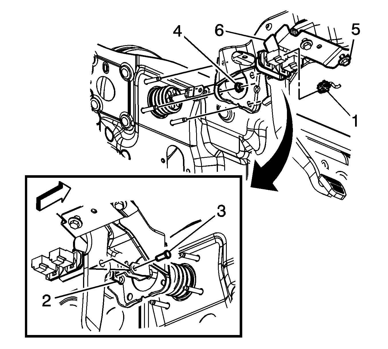
For 1990-2009 cars only
Removal Procedure
- Remove the knee bolster. Refer to Driver Knee Bolster Replacement .
- Remove the knee bolster bracket. Refer to Driver Knee Bolster Bracket Replacement .
- Disconnect the electrical connectors (1) for the brake switches. Refer to Stop Lamp Switch Adjustment .
- Lower the steering column.
- Remove the clevis pin retainer (2).
- Remove the clevis pin (3).
- Remove the mounting bolts (4) from the brake master cylinder.
- Remove the mounting bolts (5) from the cowl.
- Remove the brake pedal assembly (6).

Installation Procedure
- Install the brake pedal assembly (6) on the brake master cylinder studs.
- Finger tighten the mounting bolt (5) to the cowl.
- Install the mounting bolts (4) for the brake pedal assembly (6).
- Tighten the mounting bolts (5) to the proper specifications.
- Install the clevis pin (3) in the yoke for the brake master cylinder.
- Raise the steering column.
- Install the clevis pin retainer (2).
- Connect the electrical connectors (1) for the brake switches. Refer to Stop Lamp Switch Adjustment .
- Install the knee bolster bracket. Refer to Driver Knee Bolster Bracket Replacement .
- Install the knee bolster. Refer to Driver Knee Bolster Replacement .

Notice: Refer to Fastener Notice in the Preface section.
Tighten
Tighten the mounting bolts to 32 N·m (24 lb ft).
Tighten
Tighten the mounting bolts to 32 N·m (24 lb ft).
Tighten
Tighten the bolts to 27 N·m (20 lb ft).
