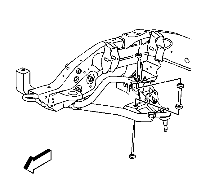
Removal Procedure
- Raise and support the vehicle. Refer to
Lifting and Jacking the Vehicle
.

- Remove
the nuts from the link bolt assemblies.
- Remove the link bolts.
- Remove the link assemblies.
Installation Procedure

- Support
the lower control arms at curb height.
- Perform the following procedure before installing the bolts:
| • | Remove all traces of the original adhesive patch. |
| • | Clean the threads of the bolt with denatured alcohol or equivalent and
allow to dry. |
| • | Apply threadlocker GM P/N 12345382 (Canadian P/N 10953489). |
- Install the link assemblies.
- Install the link bolts.
Notice: Refer to Fastener Notice in the Preface section.
Important: There are two designs of stabilizer bar links.
Use the following to identify the designs:
| • | The early design is identified by the stabilizer link bolt threads protruding
2-4 threads beyond the stabilizer shafts extruded nut. |
| • | The new design is identified by the stabilizer link bolt threads protruding
well beyond the stabilizer shafts keps nut (with washer attached. |
- Install the nuts to the link bolt assembly.
Tighten
| • | Tighten the early design nut to 14 N·m (10 lb ft).
Continue to tighten the nut until 2-4 threads protrude above the nut |
| • | Tighten the new design nut to 23 N·m (17 lb ft). |
- Lower the vehicle.


