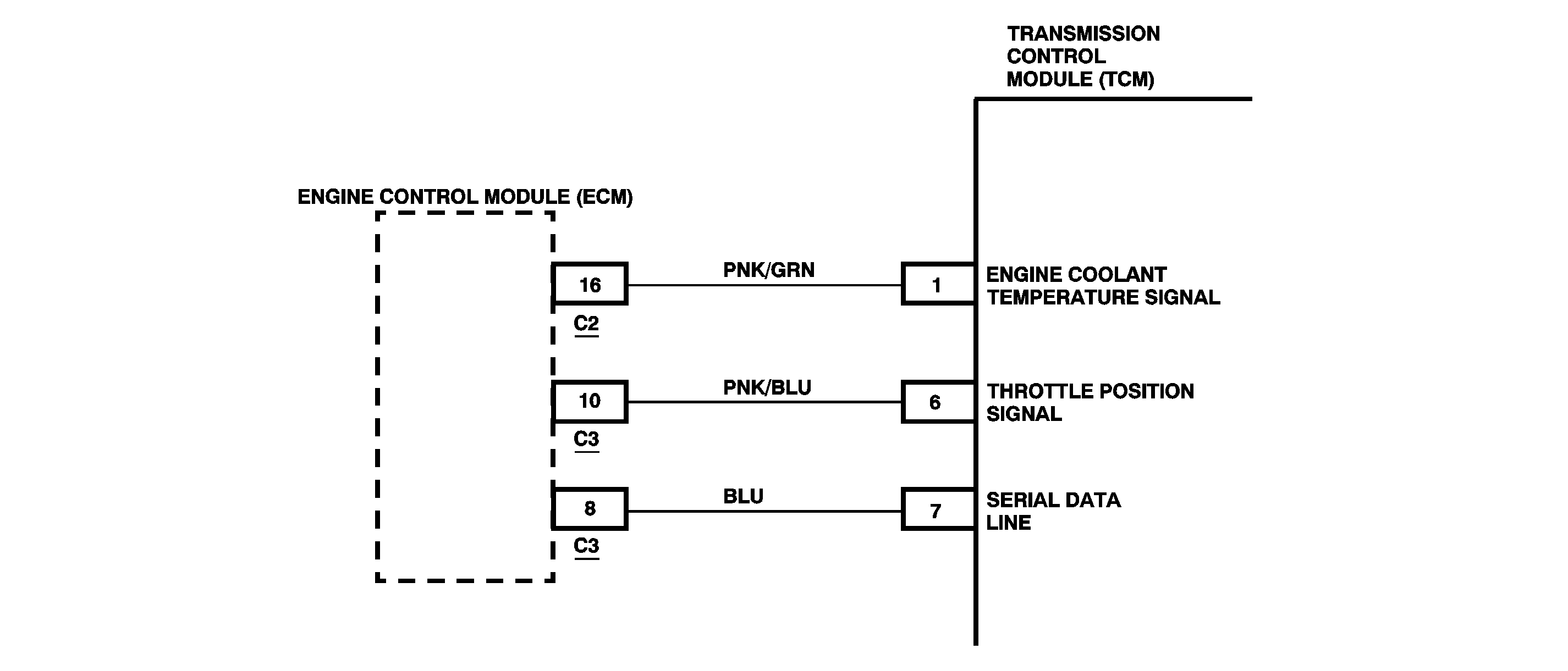
Circuit Description
The transmission control module (TCM) receives an engine coolant temperature signal from the engine control module (ECM). The TCM uses this information to delay torque converter clutch operation until the vehicle has reached an operating temperature of 30°C (86°F).
DTC Detecting Condition
The following engine coolant temperature signals are detected by the TCM while the engine running:
| • | 10 Hz (100 ms/cycle) signal being 0% ON (10-14 V) for 2.5 seconds |
| • | 10 Hz (100 ms/cycle) signal being 100% ON (about 0 V) after 15 minutes from engine start |
Action Taken When the DTC Sets
| • | DTC P1705 is stored. |
| • | The OD/OFF indicator turns ON. |
| • | The malfunction indicator lamp (MIL) turns ON. |
Diagnostic Aids
An intermittent condition may be caused by a poor connection, rubbed through wire insulation or a wire broken inside the insulation. Inspect the TCM harness connectors for backed out terminals, improper mating, broken locks, improperly formed or damaged terminals and for poor terminal-to-wire connections.
Test Description
The numbers below refer to the step numbers on the diagnostic table.
-
This step checks for DTC P0117 or DTC P0118 stored in the ECM and to proceed to their respective diagnostic charts first.
-
This step checks for proper voltage values.
-
This step checks for poor ECM connector terminal contact.
-
This step determines whether the condition is intermittent and not caused by a defective ECM.
-
This step checks for a short to ground in PNK/BLU wire.
-
This step checks for an open in the PNK/BLU wire.
-
This step determines whether the condition is intermittent and not caused by a defective TCM.
Step | Action | Value(s) | Yes | No |
|---|---|---|---|---|
1 | Was the On-Board Diagnostic (OBD) System Check performed? | -- | ||
Is DTC P0117 or DTC P0118 currently set in the ECM? | -- | Go to the applicable DTC table in Engine Controls. | ||
Is the voltage within the specified range? | 10-14 V | |||
Inspect the ECM connector C2 terminal 16 for poor contact. Is poor terminal contact or a poor connection evident? | -- | |||
Does the DTC reset? | -- | |||
Is the resistance less than the specified value? | 2 ohms | |||
Using the DVM, measure the resistance between the ECM C2 terminal 16 and TCM harness connector terminal 1. Is the resistance less than the specified value? | 2 ohms | |||
8 | Repair terminals or connection integrity that exhibits poor contact and recheck. Is the action complete? | -- | -- | |
9 | Repair the short to ground in the PNK/GRN wire between the ECM and TCM. Is the action complete? | -- | -- | |
10 | Replace the ECM. Is the action complete? | -- | -- | |
11 | Refer to Diagnostic Aids in order to correct a possible intermittent malfunction. Is the procedure complete? | -- | -- | |
12 | Repair open or high resistance in PNK/GRN wire between the ECM and TCM. Is the action complete? | -- | -- | |
Does the DTC reset? | -- | |||
14 | Replace the TCM. Is the action complete? | -- | -- | |
15 |
Does the scan tool display any DTCs? | -- | Go to the applicable DTC table | -- |
