| Table 1: | IAC Duty to Voltage Relation |
| Table 2: | Idle Speed Settings |
Idle Speed/Idle Air Control (IAC) Duty Adjustment (using a Scan Tool)
Inspection Procedure
Check following components for correct condition and operation.
Important: Before starting the engine, place the manual selector in P (automatic transaxle) or place the gearshift control lever in neutral (manual transaxle), set the parking brake and block the drive wheels.
| • | Check the accelerator cable for free movement and excessive play. Cable free play should be within specification. |
| • | Inspect the lead wires and the hoses of the Sequential Multiport Fuel Injection (SFI) and the Evaporative Emission (EVAP) control systems for being connected securely. |
| • | Check the ignition timing. Adjust the ignition timing if necessary. |
| • | Turn OFF all accessories (A/C, wipers, heater, lights, etc.). |
| • | Make sure that the Air Cleaner (ACL) is installed correctly. |
| • | Check the Air Induction system for restrictions. |
| • | Check the vacuum hoses for correct routing. Refer to the Emission Label. |
| • | Check for vacuum leaks, repair as necessary. |
Adjustment Procedure
Important:
• The IAC Calibration Mode is an internal function in the PCM and
is used to provide a base duty cycle. Therefore, when the vehicle is in the
IAC Calibration Mode the IAC Duty Cycle will read approximately 50%. But,
when in a normal idle state and reviewing the Engine Data List the IAC Duty
Cycle will read approximately 25%, this is to be considered normal operation. • If the IAC Duty remains unchanged when the adjusting screw is
turned, check the duty output terminal circuit, A/C signal circuit, PSP switch
signal circuit, PNP switch circuit (A/T) and ECT sensor performance.
- Start the engine.
- Allow the engine to reach normal operating temperature.
- Connect a scan tool.
- Using the scan tool, select IAC Calibration. This parameter is listed under Special Functions.
- Check the IAC duty cycle. The IAC duty cycle should read 50 percent with the correct engine idle speed. Refer to the Idle Speed Settings table.
- Adjust the idle speed by turning the Idle Air Control (IAC) duty adjusting screw.
- Disconnect the scan tool.
- Install the Idle Air Control (IAC) duty adjusting screw plug.
- Check the specified idle speed is obtained with the A/C ON (If equipped with A/C). Refer to Idle Speed Settings table below.
Idle Speed/Idle Air Control (IAC) Duty Adjustment (using a DMM)
Inspection Procedure
Check following components for correct condition and operation.
Important: Before starting the engine, place the manual selector in P (automatic transaxle) or place the gearshift control lever in neutral (manual transaxle), set the parking brake and block the drive wheels.
| • | Check the accelerator cable for free movement and excessive play. Cable free play should be within specification. |
| • | Inspect the lead wires and the hoses of the Sequential Multiport Fuel Injection (SFI) and the Evaporative Emission (EVAP) control systems for being connected securely. |
| • | Check the ignition timing. Adjust the ignition timing if necessary. |
| • | Turn OFF all accessories (A/C, wipers, heater, lights, etc.). |
| • | Make sure that the Air Cleaner (ACL) is installed correctly. |
| • | Check the Air Induction system for restrictions. |
| • | Check the vacuum hoses for correct routing. Refer to the Emission Label. |
| • | Check for vacuum leaks, repair as necessary. |
Adjustment Procedure
Tools Required
J 39200 Digital Multmeter
Important:
• The IAC Calibration Mode is an internal function in the PCM, and
is used to provide a base duty cycle. Therefore, when the vehicle is in the
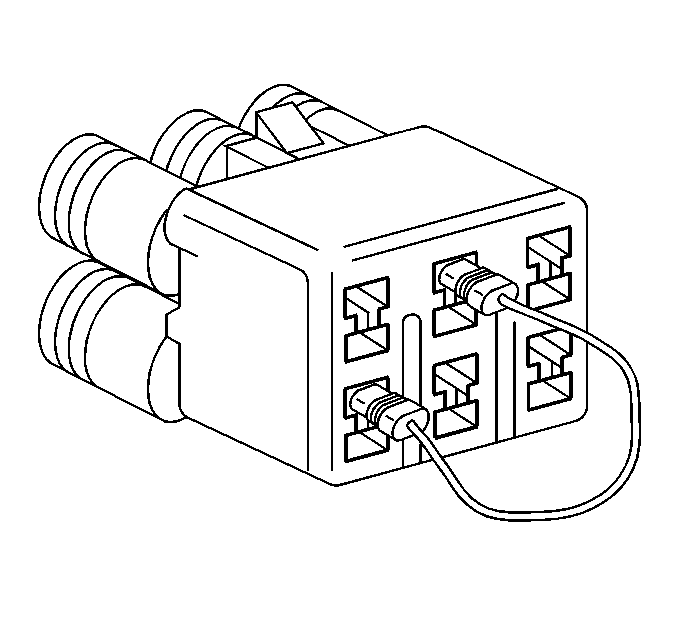
IAC Calibration Mode ( terminal 2 and 4 are jumpered on the Duty Check Data
Link Connector) the IAC Duty Cycle will read approximately 50% and may seem
to be out of specifications, this should be considered normal operation. • When the IAC Duty is OFF, the DMM will read approximately 100%
(0 volts). • When setting the IAC Duty, the duty cycle must be ON to obtain
the correct reading. • If the IAC Duty remains unchanged when the adjusting screw is
turned, check the duty output terminal circuit, A/C signal circuit, PSP switch
signal circuit, PNP switch circuit (A/T) and ECT sensor performance.
- Start the engine.
- Allow the engine to reach normal operating temperature.
- Connect a tachometer.
- Monitor the engine speed.
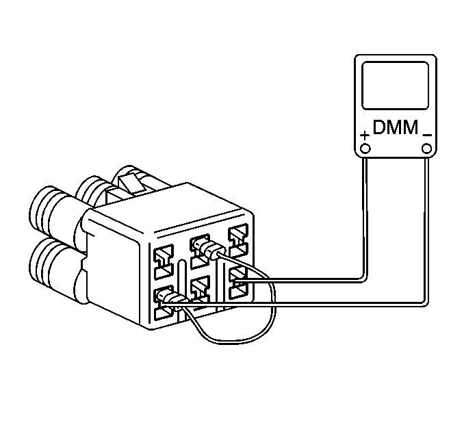
- Connect a fused jumper wire from terminal 2 (diagnostic request ) to terminal 4 (ground) of the Duty Check Data Link Connector
- Connect a J 39200 DMM from terminal 6 (duty check) to terminal 4 (ground) of the Duty Check Data Link Connector.
- Check the idle speed and the IAC duty on the DMM. The IAC duty should read 50 percent or 7 volts with the correct engine idle speed. Refer to the IAC Duty to Voltage Relation table and Idle Speed Settings Table.
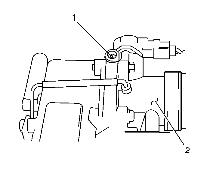
- Remove the plug over the idle air control (IAC) duty adjusting screw and adjust the idle speed by turning the IAC duty adjusting screw (1).
- Remove the fused jumper wire from the duty check data link connector.
- Disconnect the J 39200 DMM from the duty check data link connector.
- Disconnect the tachometer.
- Install the plug over the IAC duty adjusting screw .
- Check that the specified idle speed is obtained with the A/C ON (If equipped with A/C). Refer to the Idle Speed Settings table.


Important: In the table below the battery voltage represents battery voltage when the vehicle is running.
IAC Duty ON Time Indicated on DMM | IAC Duty OFF Time Indicated on DMM | Voltage Indicated on DMM |
|---|---|---|
0% | 100% | 0 volts |
50% | 50% | 0.5 x Battery Voltage |
100% | 0% | Battery Voltage |
Transmission | A/C OFF | A/C ON |
|---|---|---|
Manual | 750 - 850 RPM | 950 - 1050 RPM |
Automatic P or N | 750 - 850 RPM | 950 -1050 RPM |
Automatic R, D, 2, or L | 750 - 850 RPM | 750 - 850 RPM |
