For 1990-2009 cars only
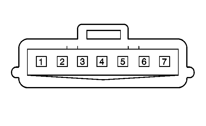
| Table 1: | Distributor |
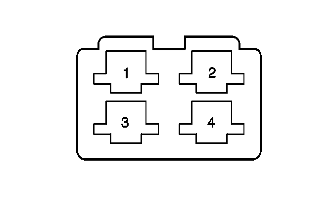
| Table 2: | Fuel Pump Relay |
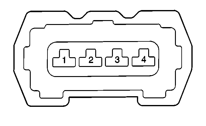
| Table 3: | Heated Oxygen Sensor 1 |
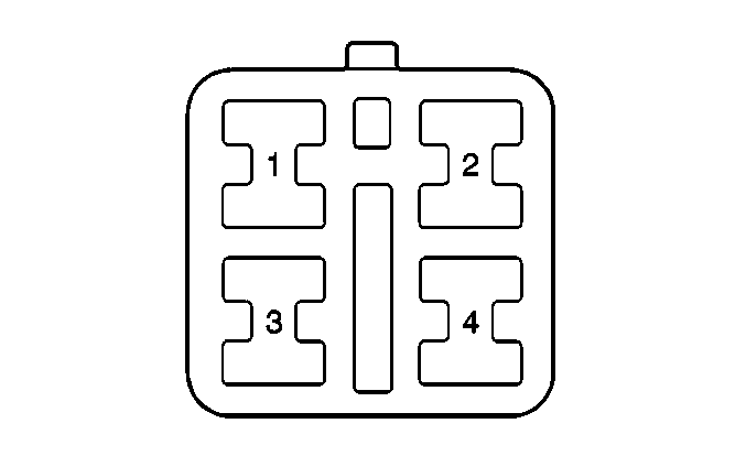
| Table 4: | Main Relay |
| Table 5: | Throttle Position (TP) Sensor |

| ||||||
|---|---|---|---|---|---|---|
Connector Part Information |
| |||||
Pin | Wire Color | Function | ||||
1 | BLK/BLU | Ground | ||||
2 | BLU/BLK | Main Relay | ||||
3 | WHT | CMP Senor Input | ||||
4 | BLK/ORN | Ground | ||||
5 | ORN | Ignition Control Module | ||||

| ||||||
|---|---|---|---|---|---|---|
Connector Part Information |
| |||||
Pin | Wire Color | Function | ||||
1 | BLK/WHT | Ignition Positive Voltage | ||||
2 | BLU/BLK | Main Relay Battery Positive Voltage | ||||
3 | PNK | Fuel Pump Relay Control | ||||
4 | PNK/BLK | Fuel Pump | ||||

| ||||||
|---|---|---|---|---|---|---|
Connector Part Information |
| |||||
Pin | Wire Color | Function | ||||
1 | WHT | Sensor Ground | ||||
2 | BLU | HO2S 1 High | ||||
3 | BLK | HO2S 1 Heater Control | ||||
4 | BLK | Ignition Positive Voltage | ||||

| ||||||
|---|---|---|---|---|---|---|
Connector Part Information |
| |||||
Pin | Wire Color | Function | ||||
1 | BLK/WHT | Ignition Positive Voltage | ||||
2 | BLK/RED | Battery Positive Voltage | ||||
3 | BLU | Main Relay Control | ||||
4 | BLU/BLK | TCC Relay Control | ||||

| ||||||
|---|---|---|---|---|---|---|
Connector Part Information |
| |||||
Pin | Wire Color | Function | ||||
1 | GRY/YEL | Ground | ||||
2 | BLU/WHT | Idle Switch Signal | ||||
3 | GRY | Throttle Position Input | ||||
4 | GRY/RED | Reference Voltage | ||||
