| Table 1: | Oxygen Sensor 1 (O2S 1) |
| Table 2: | Engine Coolant Temperature (ECT) Sensor |
| Table 3: | Intake Air Temperature (IAT) Sensor |
Oxygen Sensor 1 (O2S 1)
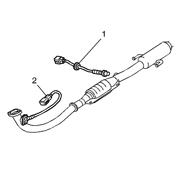
The fuel control (2) oxygen sensor 1 (O2S 1) is mounted in the exhaust pipe below the exhaust manifold. The main function of the fuel control heated oxygen sensor is to provide the powertrain control module (PCM) with exhaust stream oxygen content information. The exhaust stream oxygen content information enables the PCM to provide the proper fueling and achieve vehicle emissions that are within the mandated levels. The O2S 1 consists of the following components:
| • | A zirconia element |
| • | A cover and housing assembly |
| • | An electrical harness (pigtail wiring) |
Operation
The O2S 1 has a zirconia element with a thin platinum surface coating. The zirconia element generates an electromotive force when a there is a difference in the concentration of oxygen between its faces. This electromotive force is amplified by the catalytic reaction of the platinum when the zirconia element temperature rises. The inside of the zirconia element is exposed to the atmosphere (reference air) and the outside of the zirconia element is exposed to the exhaust gases. The difference in concentration between the inside and the outside of the zirconia element varies with the concentration of oxygen in the exhaust gases. A large difference in the concentration of oxygen results in about 1 volt of electromotive force. A small difference in the concentration of oxygen results in a about 0.01 volt of electromotive force.
In order for the O2S 1 to function properly, the sensor must have a supply of clean reference air. Clean reference air is obtained through the oxygen sensor pigtail wiring. Any attempt to repair the wires, the connectors, or the terminals of the O2S 1 pigtail wiring could result in the obstruction of the reference air. Replace the oxygen sensor if the pigtail wiring, the connector, or the terminals are damaged.
The O2S 1 voltage should constantly fluctuate from approximately 100 mV (high oxygen content -- lean mixture) to 900 mV (low oxygen content -- rich mixture). The PCM calculates what fuel mixture commands to send to the fuel injectors by monitoring the voltage output of the oxygen sensor. The oxygen sensor voltage can be monitored with a scan tool.
Air Fuel Mixture | Exhaust O2 Content | O2S 1 Output | Fuel System Response |
|---|---|---|---|
Lean Mixture | High Oxygen | Low Voltage | Rich Command |
Rich Mixture | Low Oxygen | High Voltage | Lean Command |
The oxygen sensor's ability to provide accurate and useful voltage signals can be affected by the presence of certain contaminants. The contaminants can be introduced through the fuel system or the contaminants can be airborne. Some of the contaminants that may be encountered are phosphorus, lead, silica, and sulfur. One of the more common contaminants is silica in the form of silicone. Silicone contamination may be indicated by a white powdery deposit on the portion of the O2S that is exposed to the exhaust stream. Silicone contamination can be caused by the use of gasoline with silicone in it or by the use of RTV sealants which emit silicone into the crankcase or induction system. Oxygen sensors exposed to high concentrations of engine coolant or engine oil in the exhaust stream can also be adversely affected.
The fuel control oxygen sensor 1 (O2S 1) is diagnosed for the following conditions:
| • | A slow response |
| • | An inactive signal (output steady) |
| • | A signal fixed high |
| • | A signal fixed low |
Heated Oxygen Sensor 2 (HO2S 2)

The post catalyst (1) heated oxygen sensor 2 (HO2S 2) is located in the exhaust pipe after the catalytic converter. The powertrain control module (PCM) uses the HO2S 2 in order to monitor the oxygen storage capability of the catalytic converter.
Operation
A three-way catalytic converter (TWC) is used in order to control the emissions of hydrocarbons (HC), carbon monoxide (CO), and oxides of nitrogen (NOx). The catalyst within the converter promotes a chemical reaction which oxidizes the HC and CO present in the exhaust gas. The catalyst converts the HC and CO into harmless water vapor and carbon dioxide. The catalyst also reduces NOx by converting the NOx to nitrogen. The HO2S 2 reacts to the oxygen content in the exhaust stream after it passes through the catalytic converter. The voltage signal created by the HO2S 2 sensor ranges from approximately 0.1 volt (high oxygen -- lean mixture) to 0.9 volt (low oxygen -- rich mixture). The oxygen sensor heater is required for the catalyst monitor HO2S 2 in order to become active and begin accurate catalyst monitoring. An HO2S 2 signal that appears lazy or inactive is normal. The PCM compares readings from both the O2S 1 and the HO2S 2 in order to determine the efficiency of the catalyst in the TWC converter.
In order for the HO2S 2 to function properly, the sensor must have a supply of clean reference air. Clean reference air is obtained through the oxygen sensor pigtail wiring. Any attempt to repair the wires, the connectors, or the terminals of the HO2S 2 pigtail wiring could result in the obstruction of the reference air. Replace the oxygen sensor if the pigtail wiring, the connector or the terminals are damaged.
The heater element in the oxygen sensor decreases the amount of time required for the HO2S 2 to become active. The heater also enables the sensor to remain active during long idle periods when exhaust system temperatures are lower.
The catalyst monitor heated oxygen sensor 2 (HO2S 2) is diagnosed for the following functions:
| • | A signal fixed low during steady state conditions or power enrichment (hard acceleration when a rich mixture should be indicated). |
| • | A signal fixed high during steady state conditions or decel fuel mode (deceleration when a lean mixture should be indicated). |
| • | The heater performance |
Engine Coolant Temperature (ECT) Sensor
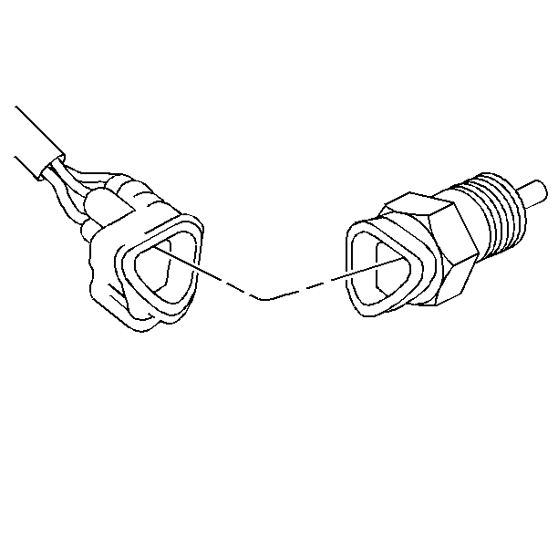
The engine coolant temperature (ECT) sensor is a thermistor (a resistor whose resistance changes as a function of temperature) and is mounted in the engine coolant stream. The ECT has two internal sensors, one portion (a single wire) controls cooling fan operation and is NOT controlled or monitored by the PCM. The other portion (two wires) is PCM monitored.
The PCM monitored portion of the ECT sensor is a two-wire sensor with a reference voltage and a ground provided by the powertrain control module (PCM). Low coolant temperature produces a high resistance and high temperatures result in a low resistance.
The PCM supplies a 5 volt signal to the coolant sensor through a resistor in the PCM and measures the signal voltage. The voltage will be high when the engine is cold and low when the engine is hot.
The ECT sensor provides engine coolant temperature information to the PCM for fuel enrichment, ignition timing, air management, idle speed control and closed loop fuel control.
Temperature | Resistance | Voltage |
|---|---|---|
Low | High | High |
High | Low | Low |
Intake Air Temperature (IAT) Sensor
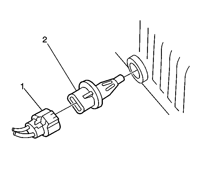
The intake air temperature (IAT) sensor (2) is mounted in the air cleaner assembly and connected to the PCM with a harness connector (1). The IAT sensor measures the temperature of the air entering the intake manifold and provides this information to the powertrain control module (PCM).
The IAT sensor is a thermistor (a resistor whose resistance changes as a function of temperature). When the temperature is low, the resistance is high. The resistance decreases as temperature increases. The IAT sensor is a two-wire sensor with a reference or signal voltage and a ground coming from the PCM.
The IAT sensor provides intake air temperature information to the PCM for use in calculating air density. The PCM uses IAT, MAP and engine speed in order to calculate the quantity of air flowing into the engine.
Temperature | Resistance | Voltage |
|---|---|---|
Low | High | High |
High | Low | Low |
Throttle Position (TP) Sensor
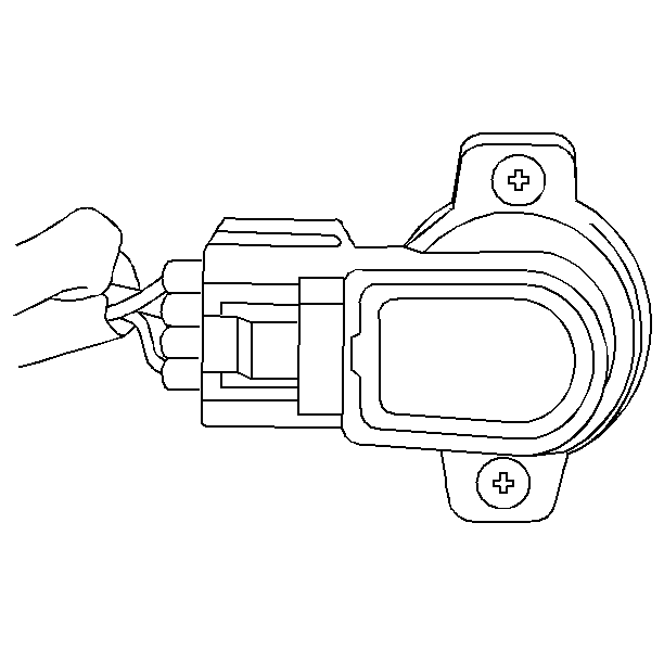
The throttle position (TP) sensor is a potentiometer connected to the throttle shaft on the throttle body. By monitoring the voltage on the signal line, the PCM calculates throttle position. As the throttle valve angle changes (accelerator pedal moved), the TP sensor signal also changes. At a closed throttle position, the output of the TP sensor is low. As the throttle valve opens, the output increases so that at wide open throttle, the output voltage should be above 3.3 volts.
By monitoring the output voltage from the TP sensor, the PCM can modify fuel delivery based on throttle angle. For example, power enrichment occurs when the throttle angle approaches wide-open throttle. The PCM looks primarily for changes in the TP sensor output to control fuel delivery. Acceleration enrichment occurs when the throttle angle increases, similar to an accelerator pump on a carbureted vehicle.
Manifold Absolute Pressure (MAP) Sensor
The MAP sensor measures the changes in the intake manifold pressure which result from engine load and speed changes. The MAP sensor converts the pressure input to a voltage output signal. The PCM provides the MAP sensor with a five volt reference voltage, a bias voltage, and a ground. The MAP sensor output signal is scaled by the bias voltage.
The manifold absolute pressure (MAP) is the opposite of manifold vacuum. When manifold pressure is high, vacuum is low. The MAP sensor is also used to calculate barometric pressure under certain conditions. This eliminates the need for a separate sensor.
As the manifold pressure changes, the electrical output of the sensor also changes. A higher pressure, low vacuum (high voltage) requires more fuel while a lower pressure, higher vacuum (low voltage) requires less fuel. By monitoring the sensor output voltage, the PCM determines the manifold pressure and can increase or decrease the ON time (or pulse width) of the injectors to allow for the addition or reduction of fuel required. The PCM also uses the MAP sensor to control ignition timing.
Vehicle Speed Sensor (VSS)
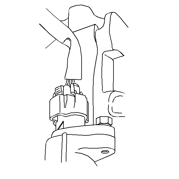
The VSS is an electronic relay that is mounted on the transaxle. As the transaxle turns the VSS, the VSS provides the speedometer with a vehicle speed input (voltage pulses). This input is used to drive the speedometer. The speedometer then converts this vehicle speed input into a more precise waveform and provides the PCM and the cruise control module (if equipped) with its own vehicle speed input. The PCM converts this input (ground pulses) into a vehicle speed.
Crankshaft Position (CKP) Sensor
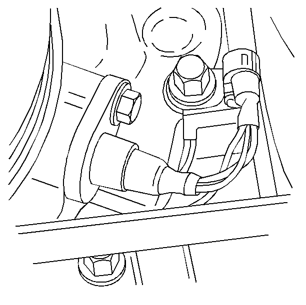
The crankshaft position (CKP) sensor is located in the front cover of the cylinder block near the crankshaft pulley. The CKP sensor produces an alternating current signal that increases in both frequency and amplitude as engine speed increases. The CKP sensor signal is sent to the powertrain control module (PCM) in order to indicate RPM and crankshaft position. The PCM uses the CKP sensor signal along with the camshaft position sensor signal in order to determine the following:
| • | Calculate fuel injector pulse. |
| • | Establish piston position (top dead center) for ignition timing. |
| • | Start the ignition coil and fuel injection sequencing. |
Operation
The CKP sensor signal rotor has 34 teeth and is mounted on the crankshaft behind the timing chain cover and the crankshaft pulley. When the crankshaft rotates, the CKP sensor signal rotor teeth pass by the CKP sensor causing a fluctuation in the sensor's magnetic field. The fluctuation in the magnetic field induces a voltage in the CKP sensor circuitry. The sensor sends this signal to the PCM at rate of 34 signals per crankshaft revolution.
Camshaft Position (CMP) Sensor
The camshaft position (CMP) sensor is located in the distributor assembly. The operation of the CMP sensor is detailed in the description of the distributor ignition system.
Knock Sensor (KS)
The knock sensor (KS) is located below the intake manifold on the side of the engine block. The KS detects engine detonation and sends a signal to the powertrain control module (PCM). The PCM uses the input from the KS to adjust ignition timing in order to control detonation. The operation of the KS is detailed in the description of the knock sensor system.
A/C On Signal
The A/C compressor control module provides an A/C On signal to the powertrain control module (PCM) when the A/C compressor clutch is in operation. The PCM uses the A/C On signal in order to adjust the fuel mixture and modify the engine idle speed. The PCM will signal the idle air control valve to open the idle air passage. Opening the idle air passage slightly will increase the engine speed in order to prevent a rough idle or a stalling condition.
Electrical Load Idle-Up Signals
The powertrain control module (PCM) receives signals from several electrical components when any of the following electrical loads are present:
| • | Rear window defogger |
| • | Headlights |
The PCM will increase the engine idle speed when receiving an electrical load input. The PCM will signal the idle air control (IAC) valve to open the idle air passage. Opening the idle air passage slightly will maintain an engine speed that provides a desirable idle. The PCM will return the engine to the original idle when the electrical load signal is removed.
Stoplamp Switch Signal
The stoplamp switch is CLOSED when the brake pedal is depressed. When closed the stoplamp switch signals the powertrain control module (PCM) that the vehicle is braking. The PCM reduces the fuel cutoff speed slightly when the stoplamp switch indicates that the vehicle is braking.
Crank Signal
The crank signal is sent from the starter motor circuit. When the starter motor circuit is energized (ignition switch in the START position), a crank signal is supplied to the PCM. The PCM increases fuel delivery (fuel injector pulse) when receiving a voltage on the crank signal circuit. The slight increase in fuel provides quicker and smoother engine start up. The crank signal is also used as an input for running certain engine control system diagnostics, such as the CKP sensor DTC P0335. The crank signal input can be monitored on a scan tool as the Starter Switch parameter.
Transaxle Range (TR) Switch Signal (A/T only)
The transaxle range switch is located on the automatic transaxle. The powertrain control module (PCM) detects the transaxle range by monitoring the ON and OFF signals from the transaxle range switch. The PCM uses the transaxle range switch signal as one of the inputs in order to control the fuel injectors, the idle air control (IAC) valve, and the automatic transaxle performance.
